Lessons · F5 LTM series · Module 3
Full explanation — same as the Techclick PDF
This section is the workbook explanation, rewritten from F5-BIG-IP-LTM-Module-3.pdf. Read it like class notes. Diagrams above are only a map — the teaching is here.
Read the PDF-order sections below. Then do the runbook. Then take the quiz. If a sentence is in the PDF, it is in this page.
PDF · page 1 — F5 BIG-IP LTM — Module 3 Virtual Servers, Pools & Load Balancing
How BIG-IP Publishes Applications and Selects Backend Servers Objective
Understand how BIG-IP LTM exposes an application to clients and distributes traffic across backend servers.
👥 Audience. Engineers who completed Modules 1 & 2 and understand Self IPs, VLANs, routing,
TMM, and basic packet flow.
- Prerequisites Management IP · Self IP · Interfaces · — VLANs · Routing · ARP · Client/Server-side networks
PDF · page 2 — Module Learning Outcomes
By the end of Module 3, you will be able to explain and configure every major LTM traffic-management object — from individual backend IP addresses all the way to the client-facing Virtual Server.
1 Objects. Define Nodes, Pool Members, Pools, and Virtual Servers — and explain how they differ.
2 Configuration. Create Nodes, Pools, and Virtual Servers via GUI and TMSH with correct production terminology.
3 Load Balancing. Configure Round Robin, Ratio, Least Connections, Priority Groups, Connection Limits, and Slow Ramp Time.
4 Verify & Troubleshoot. Use statistics, TMSH commands, and packet captures to confirm traffic flow and isolate faults.
PDF · page 3 — From Networking to Application Delivery
Module 2 gave BIG-IP reachability. Module 3 teaches BIG-IP how to publish an application and distribute client connections — the transition from network plumbing to application delivery.
Module 2 Foundation 01
Interface Physical/logical connectivity established
- 02 VLAN
Layer 2 segmentation configured 03
Self IP BIG-IP IP identity on each VLAN
- 04 Routing & ARP — Backend server reachability confirmed Module 3 Adds
- 01 Virtual Server — Client-facing listener on the VIP address 02
- Pool Logical group of backend service endpoints
- 03 Pool Member
- Individual IP + port backend target 04
LB Decision
Algorithm selects the right backend per connection
Complete path: Client → VIP → Virtual Server → Pool → Pool Member → Backend Application
PDF · page 4 — Core LTM Object Hierarchy
Every BIG-IP application-delivery configuration is built from four nested objects. Understanding how they relate to each other is the foundation of this entire module.
- Pool Members & Nodes — 10.20.20.101-103:443 and nodes Default Pool
- WEB_POOL balancing traffic Virtual Server
192.0.2.100:443 destination Node. IP address representation of a backend device (e.g., 10.20.20.101) Pool Member
- Node IP + service port inside a pool (e.g., 10.20.20.101:443) Pool — Logical collection of pool members providing the same application service
Virtual Server
Client-facing listener and full traffic-management object referencing the pool
PDF · page 5 — What Is a Node?
A Node is BIG-IP's internal representation of a backend device's IP address. It does not represent a specific TCP/UDP service — it represents the host itself. The same node can participate in multiple pools or services at different ports.
Node Identity Name: web01
- Address: 10.20.20.101 One node — multiple pool-member roles: — 10.20.20.101:80 — HTTP Pool 10.20.20.101:443 — HTTPS Pool
10.20.20.101:8080 — App Pool GUI & CLI Access. GUI: Local Traffic → Nodes → Node List tmsh list ltm node tmsh show ltm node
Remember: The Node = the IP address. It is not the service port. That distinction belongs to the Pool Member.
PDF · page 7 — What Is a Pool Member?
A Pool Member represents a specific backend application service endpoint inside a pool. It combines a Node's IP address with a service port, forming a precise destination for server-side connections.
Format IP Address : Service Port
- Example: 10.20.20.101:443 Relationship to Node — Node: 10.20.20.101 Pool Member: 10.20.20.101:443
- Multiple Members, Same Node Web01 HTTP Pool: 10.20.20.101:80
Web01 HTTPS Pool: 10.20.20.101:443. A Pool Member is always context-specific — it only exists within a pool. The same IP can appear as different pool members in different pools at different ports.
PDF · page 8 — Node vs. Pool Member — Side-by-Side
Node vs. Pool Member — Side-by-Side. This is one of the most commonly tested distinctions in F5 BIG-IP interviews and exams. Understanding it precisely is essential before configuring any pool.
Attribute Node Pool Member
- Identity IP address only IP address + service port Example 10.20.20.101 10.20.20.101:443 — Purpose Represents a backend host/device Represents a backend application service endpoint within a pool
- Multiple per IP? One node per IP address Yes — one node → many pool members across pools/ports — Exists independently? Yes — exists in node list No — only within a pool definition
Interview Question: "What is the difference between a Node and a Pool Member?" — Answer: A Node is an IP-address-only object. A Pool Member is a Node IP combined with a specific service port inside a pool. One Node can generate multiple Pool Members across different pools and ports.
PDF · page 9 — What Is a Pool?
A Pool is a logical grouping of Pool Members that collectively provide the same application or service. BIG-IP's load-balancing algorithm selects among the pool's available members for each new server-side connection.
Example: WEB_POOL. Member Name Address:Port web01 10.20.20.101:443 web02 10.20.20.102:443 web03 10.20.20.103:443
Pool Functions Member Grouping. Logical collection of backend service endpoints Load-Balancing Method
Algorithm applied to member selection Health Monitor
Determines member availability Connection Settings
Priority groups, limits, slow ramp
PDF · page 10 — Creating a Pool — GUI & TMSH
Pools are created in the Local Traffic module. Every pool requires a name, at least one member, and — in most production designs — a health monitor and load-balancing method.
- GUI Path Local Traffic → Pools → Pool List → Create
Field Value Name WEB_POOL. Health Monitor tcp or https Load Balancing Method Round Robin
- Members 10.20.20.101:443 10.20.20.102:443
10.20.20.103:443. TMSH Configuration tmsh create ltm pool WEB_POOL \ members add { 10.20.20.101:443
- 10.20.20.102:443 10.20.20.103:443
}. Verification Commands tmsh list ltm pool WEB_POOL tmsh show ltm pool WEB_POOL
A basic tcp monitor is sufficient for lab use. Detailed monitor configuration is covered in Module 5.
PDF · page 11 — Pool Member Status States
Pool Member Status States. BIG-IP tracks the operational state of each pool member. Understanding these states is critical for troubleshooting traffic distribution and diagnosing health failures.
Available / Up
Member is passing health checks and is eligible to receive new connections from the load-balancing algorithm.
Unavailable / Down
Health monitor has detected a failure. BIG-IP excludes this member from normal loadbalancing selection.
Unknown. No monitor is assigned, or the monitor has not yet returned a result. Member eligibility depends on pool configuration.
Disabled. Administratively removed from newconnection selection. May still carry existing or persisted connections depending on state.
Forced Offline
More aggressive administrative removal. Used when the member should not receive traffic under any normal circumstance.
PDF · page 12 — Disable vs. Force Offline
Disable vs. Force Offline. Both administrative states remove a pool member from normal load-balancing selection, but they differ in how aggressively they handle existing traffic. Choosing the wrong option during maintenance can impact application users.
⏸ Disable. Stops the member from receiving new connections via normal loadbalancing selection. Existing connections and certain persisted connections may continue, depending on connection and persistence state.
Best for: Graceful maintenance drain — allow in-flight sessions to complete before removing the server.
🛑 Force Offline. More aggressively removes the member from service. Intended for scenarios where you do not want any new or continuing selection of that member under normal conditions, subject to BIG-IP connection behavior.
Best for: Emergency removal or situations where a graceful drain is not required.
Production Tip: Always understand the current connection and persistence state of a pool member before taking it offline. An abrupt Force Offline on a persistence-heavy application may interrupt active user sessions.
PDF · page 13 — What Is a Virtual Server?
A Virtual Server is BIG-IP's primary traffic-management object. It listens for client connections matching configured destination criteria and applies LTM processing — profiles, policies, iRules, persistence, SNAT, and pool selection — to those connections.
- Core Identification Destination IP: 192.0.2.100
Service Port: 443 IP Protocol: TCP
Traffic Processing
- Backend Selection Default Pool: WEB_POOL — SNAT: Automap or design-specific Name: vs_web_https
Profiles (TCP, HTTP, SSL) · Persistence · iRules · LTM Policies · Source restrictions Techclick Infosec Pvt Ltd | ai.techclick.in | Training Contact: WhatsApp +91 92772
- 29456
PDF · page 14 — VIP vs. Virtual Server — Know the Difference
VIP vs. Virtual Server — Know the Difference. These terms are frequently used interchangeably in the industry, but they are not the same thing. Precise language matters when troubleshooting, documenting, or answering interview questions.
VIP / Virtual IP
The term VIP commonly refers to the destination IP address that clients connect to:
1. A VIP is just an IP address — it has no processing logic, profiles, or configuration on its own.
- Virtual Server — The Complete Object Name vs_web_https
- Destination 192.0.2.100:443 Protocol TCP — Profiles TCP · HTTP · Client SSL Pool WEB_POOL
Persistence Cookie SNAT Automap
Common Mistake: Saying "the VIP" when you mean "the Virtual Server" is imprecise. The VIP is only the IP address. The Virtual Server is the full configuration object. VIP ≠ complete Virtual Server.
PDF · page 15 — Virtual Server Matching
When a client packet arrives at BIG-IP, the system determines which Virtual Server should handle it based on three primary matching criteria:
destination IP, destination port, and IP protocol. BIG-IP selects the most specific matching Virtual Server.
Configured Virtual Servers VS Name Destination Protocol
- VS1 192.0.2.100:80 TCP VS2 192.0.2.100:443 TCP — VS3 192.0.2.200:443 TCP Traffic Matching Result
- Client Traffic Matched VS → 192.0.2.100:443 VS2 — → 192.0.2.100:80 VS1 → 192.0.2.200:443 VS3
→ 192.0.2.100:8080 No match. Advanced matching behaviors (wildcard IPs, port ranges, traffic classes) are beyond this module's scope. Focus on the three primary factors: destination IP · port · protocol.
PDF · page 16 — Creating a Virtual Server — GUI
Virtual Servers are configured in the Local Traffic module. Every field contributes to how the Virtual Server listens for traffic and processes it.
Take care to set the correct type — it determines the level of layer-7 awareness.
GUI Path: Local Traffic → Virtual Servers → Virtual Server List → Create
- Field Example Value Name vs_web_https — Destination Address/Mask 192.0.2.100/32 Service Port 443
IP Protocol TCP Virtual Server Type Standard
- Source Address Translation Automap (if required by return-path design) — Default Pool WEB_POOL Persistence Profile As required by application
Trainer Note: Walk students through each field in the GUI. Emphasize that source address translation (SNAT) configuration is driven by the return-path design — covered in detail in Module 4.
PDF · page 17 — Creating a Virtual Server — TMSH
The TMSH command below creates a basic Virtual Server. In production, additional profiles, SNAT settings, and application-specific parameters are typically required. Use this as a starting point — not a complete HTTPS configuration.
tmsh create ltm virtual vs_web_https \ destination 192.0.2.100:443 \ ip-protocol tcp \ pool WEB_POOL
- Verification Commands tmsh list ltm virtual vs_web_https tmsh show ltm virtual vs_web_https — What This Command Does Creates a Virtual Server named vs_web_https
- Listens on 192.0.2.100:443 using TCP Associates WEB_POOL as the default pool — What Is Missing for Production TCP client/server profiles
- SSL/TLS client-side profile HTTP profile (if Layer-7 processing required) — SNAT / Source Address Translation Persistence profile
Common Mistake: Treating the minimal TMSH create command as a complete HTTPS Virtual Server. Real HTTPS deployments require SSL profiles, TCP profiles, and a validated return-path design.
PDF · page 18 — Virtual Server Types Overview
BIG-IP supports several Virtual Server types, each designed for a different traffic-handling model. This module focuses on Standard, Performance Layer 4, and Forwarding IP. The others are introduced at a high level for awareness.
Type Primary Use Case Key Characteristic
Standard Full-proxy application delivery with Layer-7 processing
- Terminates client connection; establishes independent server-side connection — Performance (L4) High-throughput TCP/UDP forwarding FastL4 profile; reduced Layer-7 awareness
- Forwarding (IP) Controlled IP forwarding without pool-based load balancing — BIG-IP forwards packets; no pool required in standard model
- Forwarding (Layer 2) Layer-2 bridging use cases Bridges traffic at L2 — Reject Explicit traffic rejection Returns RST or ICMP unreachable to client
Stateless Stateless UDP or IP-in-IP forwarding No connection table maintained
Detailed teaching focus for this module: Standard → Performance L4 → Forwarding IP. All other types are awareness-level only at this stage.
PDF · page 19 — Standard Virtual Server — Full Proxy
The Standard Virtual Server is the most commonly used type for application delivery. It operates as a full proxy: BIG-IP terminates the clientside TCP connection and independently establishes a separate server-side TCP connection to the selected pool member.
Full Proxy Two-
- Connectio n Model BIG-IP (Proxy) — 192.0.2.100:443 terminates Session 1 BIG-IP to Server
Establishes independent TCP Session 2
- Web01 10.20.20.101:443 receives Session 2
- Client 198.51.100.50 initiates
TCP Session 1 Client-Side Connection
- Client → BIG-IP VIP BIG-IP handles TCP, TLS negotiation, and
HTTP processing on behalf of the client.
- Server-Side Connection BIG-IP → Selected Pool Member
A completely independent TCP session.
BIG-IP can re-use, multiplex, or optimize server-side connections independently.
Full Proxy Capabilities
SSL Termination · HTTP Inspection · iRules · Persistence · Server-side TCP
- Optimization · Layer-7 Policies
PDF · page 20 — Performance Layer 4 Virtual Server
The Performance Layer 4 Virtual Server uses the FastL4 profile for optimized Layer-4 TCP/UDP processing. It trades some Layer-7 feature depth for higher throughput — a valid design choice when application-layer inspection is not required.
Standard Virtual Server Full proxy — two independent TCP sessions
Complete Layer-7 feature set HTTP profiles, SSL termination, iRules
- Per-request persistence and policy inspection Independent client/server TCP profiles — Performance Layer 4 Virtual Server FastL4 profile for optimized L4 processing
High-throughput TCP/UDP forwarding Reduced Layer-7 awareness
- HTTP and SSL profiles are not applicable in the same way Useful when L7 features are not required — Common Mistake: Assuming Performance L4 is always faster than Standard for every workload. The right choice depends on whether
Layer-7 processing is required by the application design. Do not select Performance L4 when HTTP or SSL inspection is needed.
PDF · page 21 — Forwarding IP Virtual Server
A Forwarding IP Virtual Server instructs BIG-IP to forward IP traffic rather than load-balance it to a pool in the standard application-delivery model. It is used when BIG-IP sits in a routed network path and traffic must traverse it without pool-based distribution.
Topology Example Network B
BIG-IP Forwarding IP VS Network A
Typical Use Cases Controlled Forwarding
BIG-IP in a routed path needs to allow specific traffic to pass through to another network segment.
No Pool Required
Traffic is forwarded to its original destination — no poolbased member selection takes place.
Not for Typical Web Apps
Forwarding IP is not the standard choice for publishing a load-balanced web application. Use Standard VS for that.
PDF · page 22 — The Load-Balancing Decision
Every time a new server-side connection must be established, BIG-IP's load-balancing engine evaluates the available pool members and selects one based on the configured algorithm. Health state, connection limits, priority groups, and slow ramp all influence eligibility before the algorithm runs.
Apply Algorithm
Evaluate MembersDefault PoolVirtual
Match Client
Connect Eligibility First
Health monitors, connection limits, priority groups, and administrative state determine which members are eligible candidates.
Algorithm Second The configured load-balancing method
(Round Robin, Ratio, Least Connections, etc.) selects among the eligible members.
Connection Scope
Load-balancing decisions are generally associated with server-side connection or member selection — not necessarily individual HTTP requests unless connection behavior allows it.
PDF · page 24 — Round Robin Load Balancing
Round Robin distributes new server-side connection selections sequentially across available pool members. It is the default and simplest algorithm — useful when backend servers have similar capacity and workload characteristics.
Selection Sequence — 6 Connections Connection Selected Member
- 1 Web01 2 Web02
- 3 Web03 4 Web01 (cycle repeats)
- 5 Web02 6 Web03
Important Nuances Connection Reuse
Browser keep-alive and persistent TCP connections may cause multiple HTTP requests to travel over a single server-side connection — making observed distribution appear uneven.
Persistence
If persistence is enabled, a returning client may be pinned to the same member regardless of Round Robin turn order.
Best For. Homogeneous backends with similar CPU, RAM, and requesthandling capability.
PDF · page 25 — Ratio Load Balancing
Ratio allows administrators to assign relative weights to pool members. Members with higher ratios receive proportionally more new server-side connection selections. This is ideal when backend servers have different capacity levels.
Configuration Example Member Ratio Weight
Web01 3 Web02 1
Over a representative set of 8 selections:
Selection Member 1, 2, 3 Web01
- 4 Web02 5, 6, 7 Web01
- 8 Web02 When to Use Ratio
Heterogeneous Capacity
Web01 has more CPU/RAM than Web02 — assign a higher ratio to direct more connections to it.
Tiered Hardware
Newly upgraded servers can receive a higher share; older servers are weighted down during phased upgrades.
Gradual Migration
Shift traffic weight from legacy to new servers incrementally by adjusting ratios over time.
Actual distribution is approximate over time and subject to connection reuse, availability, and persistence state — not a guaranteed per-connection mathematical split.
PDF · page 26 — Least Connections Load Balancing
Least Connections directs new server-side connection selections to the eligible member currently carrying the fewest active connections. It adapts to real-time backend load — particularly useful where connection durations vary significantly across requests.
Example State Member Active Connections
- Web01 100 Web02 40 ← Selected — Web03 65 New connection → Web02 (lowest active count)
- Member vs. Node Variants Least Connections Member — Counts connections at the pool-member level (IP + port). Most common selection for pool-based comparisons.
Least Connections Node
Counts connections at the node (IP) level across all pool memberships of that node. Useful when one server participates in multiple pools.
Best For. Workloads with variable connection duration — e.g., mixed short and long-lived connections where Round Robin would create imbalance.
PDF · page 27 — Other Load-Balancing Methods
BIG-IP supports several additional load-balancing methods beyond the core three. These are introduced here at an awareness level — they are not commonly required in beginner labs but may appear in production environments and interviews.
Method Basic Idea When Useful
- Ratio Member Weighted distribution at the member level Heterogeneous server capacity within a pool — Ratio Node Weighted distribution at the node (IP) level Node participates in multiple pools with unequal capacity
Least Connections Node Fewest connections across all memberships of a node
Multi-pool environments where total node load matters
- Fastest Selects member with fastest response time Geographically or performance-varied backends — Observed Combines connection count and response time dynamically Dynamic workloads with variable performance
Predictive Uses trends from Observed method to anticipate best member Workloads with predictable performance patterns For the lab and most production HTTP/HTTPS applications, Round Robin, Ratio, and Least Connections cover the vast majority of use cases. Explore Fastest, Observed, and Predictive when backend performance varies significantly.
PDF · page 29 — Priority Group Activation
Priority Group Activation enables an active/backup pool-member design within a single pool. Members are assigned to priority groups — higher-priority groups receive traffic first. Lower-priority members only become eligible when the available capacity in higher-priority groups drops below a configured activation threshold.
Configuration Example Member Priority Group
- Web01 10 (Primary) Web02 10 (Primary)
- Web03 5 (Backup) — Normal operation: Web01 + Web02 receive all traffic.
Failure condition: When available priority-10 members fall below the configured threshold, Web03 becomes eligible.
Use Cases Primary / DR Design
Primary datacenter members in group 10; DR datacenter members in group 5. DR only activates on primary failure.
Capacity Overflow
Overflow members absorb traffic only when preferred capacity is exhausted — protecting high-cost or limited resources.
Controlled Failover
Maintains service continuity without requiring separate pools or iRules logic for primary/backup selection.
PDF · page 30 — Connection Limits
Connection limits cap the maximum number of concurrent connections allowed to a node, pool member, or Virtual Server. When a limit is reached, BIG-IP selects other eligible members where possible, protecting backend servers from being overwhelmed.
Node-Level Limit
Applies to the total connections across all pool memberships for a given IP address.
Protects the physical host regardless of which pool is sending traffic.
Pool Member-Level Limit. Applies to a specific IP:port combination within a pool. Allows fine-grained perservice capacity enforcement on the same host.
Virtual Server-Level Limit
Caps total concurrent connections accepted by the Virtual Server. Useful for rate-limiting an entire published service.
Example Web01 pool member maximum: 1,000 connections
When reached → BIG-IP selects Web02 or Web03 for new connections (where eligible).
Production Caution
Setting limits too low creates unnecessary connection refusals.
Setting them too high defeats the purpose. Always baseline actual server capacity before configuring limits in production.
PDF · page 31 — Slow Ramp Time
Slow Ramp Time protects a pool member that has just become available from immediately receiving its full share of new connections. Traffic is gradually increased over a configured time period, giving the backend application time to warm up before handling peak load.
Without Slow Ramp Return from MaintenanceWeb01 becomes available
Immediate Full TrafficReceives full share, risking overload With Slow Ramp
- Web01 ReturnsInstance becomes healthy after maintenance Slow RampTraffic share increases gradually over time — Full TrafficInstance receives its full safe share Applications That Benefit from Slow Ramp
JVM / App Servers
Java applications require JIT compilation warmup before reaching full performance.
Sudden load causes GC spikes.
Database Connection Pools
Application servers that lazily initialize DB connections need time to establish their pool before full traffic arrives.
Caches & CDN Origins
Cold-start cache misses create high backend load. Slow ramp allows cache population before full traffic exposure.
PDF · page 32 — Health Monitor Relationship
Health monitors determine whether a pool member is eligible to receive traffic. BIG-IP sends periodic probes to backend services; failing members are removed from load-balancing selection until they recover. Detailed monitor configuration is covered in Module 5 — this section introduces the concept only.
- How It Works BIG‑IP Sends Probe Web01 Responds Healthy — Member Remains EligibleNo Response → Marked Down Common Monitor Types
- 443 — Trainer Note: Use a basic tcp or http monitor for the lab.
Monitor What It Checks tcp TCP port open and accepting connections http HTTP response code from port 80 https HTTPS response from port Interval, timeout, receive strings, and custom send strings are covered in Module 5.
PDF · page 33 — Complete Application Traffic Flow
This 10-step sequence traces a client connection from DNS resolution through the BIG-IP Virtual Server, pool selection, backend processing, and response delivery. This is the core packet flow every engineer must internalize.
Client Side Client: 198.51.100.50. DNS: www.example.com → 192.0.2.100 Virtual Server: 192.0.2.100:443
Server Side Pool: WEB_POOL. Members: 10.20.20.101:443 · .102:443 · .103:443 Selected: Algorithm-determined eligible member
PDF · page 34 — Statistics & Verification
BIG-IP provides rich real-time and cumulative statistics for Virtual Servers, Pools, and Nodes. Reviewing statistics is the first step in verifying correct traffic distribution and diagnosing issues without a packet capture.
GUI — Statistics Paths
- Virtual Servers: Local Traffic → Virtual Servers → Statistics Pools: Local Traffic → Pools → Statistics — Nodes: Local Traffic → Nodes → Statistics Key Metrics — Virtual Server
Current Connections Total Connections
Bits/Bytes In and Out Packets In and Out
- Key Metrics — Pool & Members Member Status (Green/Red/Gray) — Current Connections per Member Total Connections per Member
Traffic Distribution across Members
TMSH Verification Commands tmsh show ltm virtual tmsh show ltm pool tmsh show ltm pool WEB_POOL members tmsh show ltm node
Production Tip: Compare per-member connection counts to verify load-balancing distribution is working as expected. Unequal distribution may indicate persistence, failed members, or misconfigured ratios.
PDF · page 35 — Packet Capture for VIP Testing
When statistics show unexpected behavior or traffic is not reaching backends, packet captures on BIG-IP confirm exactly what is arriving at the VIP and what is leaving toward backend servers. Two capture points — client-side and server-side — isolate the fault location.
Capture Commands tmsh run util bash
- # Client-side capture tcpdump -nni 0.0 host 198.51.100.50 — # Server-side capture tcpdump -nni 0.0 host 10.20.20.101
# Port-based capture tcpdump -nni 0.0 port 443. # Combined filter tcpdump -nni 0.0 \ 'host 198.51.100.50 or \ host 10.20.20.101'
Two Capture Points Client Capture BIG-IP CaptureBackend Capture
Interpretation Guide
- Traffic at A, not at B: VIP matched, but no server-side flow — check pool, member state, iRule, policy — Traffic at B, no response: Backend not answering — check server, firewall, ARP, VLAN
No traffic at A: Routing, VLAN, or reachability issue before BIG-IP
PDF · page 36 — Chapter Break — Hands-On Labs MODULE 3 LAB SECTION
Put It Into Practice
The following lab exercises reinforce every concept taught in Module 3. Students will configure nodes, pools, Virtual Servers, and loadbalancing algorithms — then verify and troubleshoot live traffic using statistics and packet captures.
Labs 1–2. Create backend objects (nodes, pool, members) and publish with a Virtual Server
Labs 3–4. Test Round Robin distribution and simulate member failure Labs 5–6
- Configure Ratio and Least Connections; compare observed behavior Lab 7 — Practice Disable and Force Offline for controlled maintenance scenarios
PDF · page 37 — Lab Topology
All Module 3 labs use the following VMware-based topology. Each web server displays its hostname in the HTTP response body — making load-balancing behavior directly visible in the browser or via curl.
Lab Network
Topology Client VM
- 198.51.100.50 generates HTTP requests
- External VLAN VLAN 10 192.0.2.0/24,
VIP 192.0.2.100:80 BIG-IP VE. External self 192.0.2.10, internal self 10.20.20.10 Web Servers
- Web01/02/03 10.20.20.101-103:80
Client VM
- 198.51.100.50 — generates HTTP connections via browser or curl BIG-IP VE — External Self: 192.0.2.10 VIP: 192.0.2.100:80
- Internal Self: 10.20.20.10 Web Servers — Web01: 10.20.20.101:80 Web02: 10.20.20.102:80
Web03: 10.20.20.103:80. Lab Task: Before beginning, confirm each web server displays its own hostname (WEB01, WEB02, WEB03) in the HTTP response. This makes load-balancing distribution directly observable.
PDF · page 38 — Lab 1 — Create Backend Objects LAB TASK
Create the three nodes representing your backend web servers, then build WEB_POOL with all three members. A basic health monitor ensures BIG-IP can detect backend failures during subsequent labs.
- Step 1 — Create Nodes GUI: Local Traffic → Nodes → Node List → Create — Name Address web01 10.20.20.101 web02 10.20.20.102 web03 10.20.20.103 Step 2 — Create WEB_POOL
GUI: Local Traffic → Pools → Pool List → Create tmsh create ltm pool WEB_POOL \ monitor tcp \ load-balancing-mode \ round-robin \ members add {
- 10.20.20.101:80 10.20.20.102:80
10.20.20.103:80 }. Verify: All three members show green/Available in the pool member list before proceeding.
PDF · page 39 — Lab 2 — Create the Virtual Server LAB TASK
Create a Standard Virtual Server that listens on the VIP address and distributes traffic to WEB_POOL. Configure Source Address Translation only if required by the lab's return-path design.
Configuration Values Field Value
- Name vs_web_http Destination 192.0.2.100/32
Service Port 80 Protocol TCP
- Type Standard Default Pool WEB_POOL — SNAT Automap (if return path requires it)
TMSH Command tmsh create ltm virtual \ vs_web_http \ destination 192.0.2.100:80 \ ip-protocol tcp \ pool WEB_POOL \ source-address-translation \
{ type automap }. Verification tmsh list ltm virtual vs_web_http tmsh show ltm virtual vs_web_http
Test immediately: curl http://192.0.2.100/ from the client VM.
You should see WEB01, WEB02, or WEB03 in the response body.
PDF · page 40 — Lab 3 — Test Round Robin & Lab 4 — Member Failure LAB TASKS 3 & 4
Lab 3 — Round Robin Observation
Generate multiple independent client connections and observe which backend responds.
# Use curl to force new connections for i in {1..9}; do curl -s http://192.0.2.100/ \
| grep -i hostname done. Expected: Responses rotate through WEB01 → WEB02 → WEB03 → WEB01 etc.
Common Mistake: Using a browser may not show Round
Robin — browsers reuse keep-alive connections. Always use curl or set Connection: close headers to generate separate server-side connections.
Lab 4 — Simulate Member Failure
Stop the web service on Web02 and observe how BIG-IP responds.
Stop the HTTP service on Web02 (10.20.20.102)1.
Wait for the health monitor to detect the failure (monitor interval)2.
Observe Web02 status change to red/Unavailable in Pool statistics 3.
Run curl loop again — confirm Web02 never responds4.
Restore Web02 service and observe recovery5.
PDF · page 41 — Labs 5, 6 & 7 — Ratio, Least Connections & Maintenance LAB TASKS 5, 6 & 7
1 Lab 5 — Ratio. Set Web01 ratio = 3, Web02 ratio = 1. Run 8+ curl connections and observe that
Web01 receives approximately 3x more selections than Web02. Compare pool statistics before and after ratio change.
2 Lab 6 — Least Connections. Generate concurrent connections (use ab or siege if available). Change pool LB method to Least Connections Member.
Observe connection distribution in pool statistics — the member with fewer active connections should receive preference.
- 3 Lab 7 — Disable vs. Force
Offline. Disable Web01: Generate traffic, confirm new connections go to Web02/Web03 only. Check if any existing connections drain. Re-enable and verify recovery.
Force Offline Web01: Repeat and compare the aggressiveness of the two administrative removal methods.
Packet Flow: During each lab, run a parallel tcpdump capture to confirm server-side connections are only going to healthy/enabled members. No SYN toward a disabled or failed member should appear in Capture B.
PDF · page 42 — Chapter Break — Troubleshooting TROUBLESHOOTING SECTION
Diagnose & Resolve
The following six troubleshooting scenarios cover the most common Virtual Server, Pool, and Pool Member problems encountered in production BIG-IP environments. Work through each scenario using the systematic check sequence provided.
PDF · page 43 — Troubleshooting — Scenarios 1 & 2 🔴 Scenario 1: VIP Does Not Respond
- Troubleshooting — Scenarios 1 & 2 🔴 Scenario 1: VIP Does Not Respond — Client cannot connect to 192.0.2.100:80 at all — connection times out or is refused.
Check in order:
Destination address and service port match the Virtual Server configuration
1.
IP protocol (TCP vs UDP) is correct2.
VLAN/network reachability — can you ping the VIP from the correct VLAN?
3.
Virtual Server is enabled (not disabled)4.
Pool availability — at least one member must be up5.
Routing from client to VIP subnet6.
SNAT/return-path configuration where applicable7.
🟡 Scenario 2: VS Available, Pool Down. Virtual Server is green but the application returns errors — pool has no available members.
Check in order:
Pool member status — any member green?1.
Health monitor results — what is the monitor reporting?2.
Backend service running on each server (port listening?)3.
Routing from BIG-IP to backend VLAN4.
Firewall rules between BIG-IP internal Self IP and backend servers5.
Correct service port configured on pool members6.
tmsh show ltm pool WEB_POOL members tmsh show ltm node
PDF · page 44 — Troubleshooting — Scenarios 3, 4 & 5 🟠 Scenario 3: One Server Gets
- Troubleshooting — Scenarios 3, 4 & 5 🟠 Scenario 3: One Server Gets — All Traffic Symptoms: All curl responses return
WEB01 only.
- Web02/Web03 actually up?) · Ratio weights (verify ratios are not zero for other members) · Priority Group — Activation (backup group active?) · Browser reusing keep-alive connections
- (use curl instead) 🔴 Scenario 4: Client SYN — Arrives, No Server-Side SYN Symptoms: Capture A shows client
Check: Persistence (cookie/source IP pinning all clients) · Load-balancing method setting · Member availability (are SYN; Capture B shows nothing toward backend.
- Check: Virtual Server matching (destination IP/port/protocol correct?) · — Default pool configured on the VS · All pool members down (monitor failure?) · iRule or LTM Policy redirecting or dropping traffic · Return-path or SNAT configuration · Route from BIG-IP to backend network
🟡 Scenario 5: BIG-IP Sends SYN, Backend Silent. Symptoms: Capture B shows SYN to backend; no SYN-ACK received.
- Check: Backend server actually listening on the configured port · Firewall blocking BIG-IP internal Self IP — → backend · ARP resolution for backend IP (check arp -a on BIG-IP) · Correct
- VLAN assignment · Backend route back to BIG-IP internal Self IP
PDF · page 45 — Troubleshooting — Scenario 6 & Summary Flow 🔴 Scenario 6: Backend Replies, Client Fails
- Troubleshooting — Scenario 6 & Summary Flow 🔴 Scenario 6: Backend Replies, Client Fails — Symptoms: Backend responds to BIG-IP (Capture B confirms this), but the client receives no valid response or gets a RST.
Check in order:
Return path — does the backend route its responses back through BIG-IP?
1.
SNAT configuration — without SNAT, backend may respond directly to client, bypassing BIG-IP and breaking the TCP state machine (asymmetric routing) 2.
Profile mismatch — HTTP or SSL profile issues causing BIG-IP to reject the server response 3.
Connection state — does BIG-IP still have a valid client-side connection entry?
4.
- Troubleshooting Decision Flow Return path OK?Check SNAT and profiles — Is traffic distributed?Check LB method and persistence Is pool up?Check members and monitor
- Is VIP reachable?Verify VS and routing — Remember: Always check the most recent entries in
/var/log/ltm for additional context on connection failures and Virtual Server processing errors.
PDF · page 46 — Interview Questions — Part 1 INTERVIEW PREP
These 25 questions cover the most commonly asked BIG-IP LTM topics in technical interviews and certification exams. Review each answer until you can explain it confidently without notes.
Q1. What is a Node?
A Node is BIG-IP's representation of a backend device's IP address. It does not include a service port — it represents the host only (e.g., 10.20.20.101).
Q2. What is a Pool Member?
A Pool Member is a specific backend service endpoint inside a pool, defined as an IP address combined with a service port (e.g., 10.20.20.101:443).
Q3. Node vs. Pool Member?
A Node is IP-only. A Pool Member is IP + service port within a pool. One Node can generate multiple Pool Members across different pools and ports.
- Q4. What is a Pool? A Pool is a logical group of Pool — Members that provide the same application or service. It holds the loadbalancing method, health monitors, priority groups, and connection settings.
Q5. What is a Virtual Server?
A Virtual Server is a BIG-IP trafficmanagement object that listens for client connections matching destination IP, port, and protocol criteria, and applies LTM processing (profiles, policies, pool selection, SNAT, persistence, iRules).
PDF · page 47 — Interview Questions — Part 2 INTERVIEW PREP
Q6. VIP vs. Virtual Server?
- VIP refers only to the destination IP address (e.g., 192.0.2.100). The Virtual — Server is the complete configuration object: destination, port, protocol, profiles, pool, persistence, SNAT, and more. VIP ≠ Virtual Server.
Q7. What identifies a Virtual Server?
Three primary factors: destination IP address, destination service port, and IP protocol. BIG-IP selects the most specific matching Virtual Server for incoming traffic.
Q8. What is a Standard Virtual Server?
A Standard Virtual Server is the most common type for application delivery. It operates as a full proxy — terminating the client TCP session and establishing an independent server-side TCP session to the selected pool member.
Q9. What does full proxy mean?
Full proxy means BIG-IP maintains two separate TCP connections: one with the client and one with the backend server.
This allows independent processing of each side — enabling SSL termination,
HTTP inspection, iRules, and server-side optimization.
Q10. Standard vs. Performance L4?
Standard VS = full proxy with Layer-7 features (HTTP, SSL, iRules).
- Performance L4 VS = FastL4-optimized Layer-4 processing with reduced Layer- — 7 awareness. Use Performance L4 only when application-layer processing is not required.
PDF · page 48 — Interview Questions — Part 3 INTERVIEW PREP
- Q11. What is Forwarding IP VS? A Forwarding IP Virtual Server instructs — BIG-IP to forward IP traffic to its original destination rather than load-balancing to a pool. Used when BIG-IP is in a routed path and normal application delivery is not required.
Q12. What is Round Robin?
Round Robin distributes new server-side connection selections sequentially across available pool members. Simple and effective for backends with similar capacity. Connection reuse and persistence can affect observed distribution.
Q13. What is Ratio load balancing?
Ratio assigns relative weights to pool members. A member with a ratio of 3 receives approximately 3 times more selections than a member with ratio 1.
Used when backends have different capacity levels.
Q14. What is Least Connections?
Least Connections selects the eligible member with the fewest active connections. It adapts to real-time backend load — particularly useful when connection durations vary significantly across requests.
Q15. When would you use Least Connections?
When connection duration varies significantly across requests — e.g., mixed short and long-lived connections.
Round Robin may send equal selections but create unequal active-connection load on different backends.
PDF · page 49 — Interview Questions — Part 4 INTERVIEW PREP
Q16. What is Priority Group Activation?
Priority Group Activation assigns pool members to numbered priority groups.
Higher-priority members receive traffic first. Lower-priority (backup) members only become eligible when available higher-priority capacity drops below the configured activation threshold.
Q17. What is Slow Ramp Time?
Slow Ramp Time gradually increases traffic toward a newly available pool member over a configured period, preventing it from being overwhelmed immediately after returning from maintenance or startup — especially important for JVM, cache, and DBheavy applications.
Q18. Disable vs. Force Offline?
Disable: gracefully stops new connection selection while allowing certain existing/persisted connections to continue. Force Offline: more aggressively removes the member — used when you want the member out of service without waiting for a graceful drain.
- Q19. What happens when a pool member fails a health check? BIG-IP marks the member as — Unavailable/Down and excludes it from load-balancing selection. New connections go to remaining healthy members. If no members are available, the pool is marked down and the Virtual
Server may return a service-unavailable response.
Q20. How do you check pool statistics? GUI: Local Traffic → Pools → Statistics.
CLI: tmsh show ltm pool WEB_POOL members. Review per-member connection counts, traffic distribution, and status indicators to verify correct behavior.
PDF · page 50 — Interview Questions — Part 5 INTERVIEW PREP
Q21. How do you check Virtual Server statistics?
GUI: Local Traffic → Virtual Servers →. Statistics. CLI: tmsh show ltm virtual or tmsh show ltm virtual vs_web_https.
Review current connections, total connections, bytes, and packets.
Q22. VIP is reachable but app not working — what do you check?
1) Pool member availability (any green members?). 2) Health monitor results. 3)
Backend service on correct port. 4). Return path / SNAT. 5) Profiles matching application requirements. 6) iRule or
LTM policy intercepting traffic. 7) /var/log/ltm for errors.
Q23. Why might browser testing not show perfect Round Robin?
Browsers use HTTP keep-alive, which reuses an existing server-side TCP connection for multiple requests.
- Multiple HTTP requests travel over a single persistent connection to one backend. Use curl or explicitly set — Connection: close to force new connections per request.
Q24. Can one Node have multiple Pool Members?
- Yes. One Node (IP address) can appear as multiple Pool Members across different pools and ports. Example: — Node 10.20.20.101 → Member 10.20.20.101:80 in HTTP Pool and
Member 10.20.20.101:443 in HTTPS Pool.
- Q25. What happens if no pool members are available? The pool is marked down. The Virtual — Server associated with that pool may return an error to the client (connection refused, RST, or HTTP 503 depending on profiles and configuration). No server-side connections can be established until at least one member recovers.
PDF · page 51 — Module 3 — Complete Architecture Summary
The complete end-to-end architecture of a BIG-IP LTM application delivery flow — from client DNS resolution to backend application response — built from every object and concept covered in this module.
PDF · page 53 — Module 3 Revision Checklist SELF-ASSESSMENT
Before moving to Module 4, confirm you can explain and configure each item below without referring to notes. If any item is unclear, revisit the relevant section.
Objects & Configuration Node — IP-only representation of a backend host
- Pool Member — IP + service port within a pool Pool — logical group of Pool Members — Virtual Server — complete client-facing LTM object VIP vs. Virtual Server distinction
- Virtual Server matching (IP, port, protocol) Create nodes, pools, and VS via GUI and TMSH — Standard VS — full proxy, two TCP sessions
- Performance L4 VS — FastL4, reduced L7 awareness Forwarding IP VS — no pool, forward traffic — Load Balancing & Operations Round Robin — sequential selection
- Ratio — weighted proportional distribution Least Connections — fewest active connections — Priority Group Activation — primary/backup design Connection Limits — node, member, VS levels
Slow Ramp Time — gradual traffic increase on recovery
- Disable vs. Force Offline — maintenance operations — Pool member status states (Up/Down/Disabled/Forced) Statistics verification via GUI and TMSH
Packet capture — two capture points (client/server side) Troubleshoot VIP, pool, and member problems
PDF · page 54 — Up Next — Module 4 Profiles, SNAT, Persistence & SSL/TLS
Module 3 gave you the complete foundation for publishing and load-balancing applications. Module 4 builds on that by teaching how BIG-IP processes those connections in depth — controlling TCP behavior, ensuring correct return-path routing, maintaining client affinity, and terminating SSL/TLS.
Profiles. TCP, HTTP, and OneConnect profiles — how they shape client and server-side connection behavior on a Standard Virtual Server.
SNAT. Source Network Address Translation — ensuring backend servers route responses back through BIG-IP. Automap, SNAT Pools, and design considerations.
Persistence
Cookie, Source IP, and SSL Session ID persistence — keeping clients pinned to the same backend server across multiple connections.
SSL/TLS. Client SSL and Server SSL profiles — SSL termination, reencryption, and certificate management on BIG-IP LTM.
Same lab numbers on every page: client 198.51.100.50, VIP 192.0.2.100, Self IPs 192.0.2.10 / 10.20.20.10, members 10.20.20.101–103.
- Hub · Course map
- M1 · Fundamentals & admin
- M2 · Networking & traffic flow
- M3 · Virtual Servers & pools ← you are here
- M4 · Profiles, SNAT, SSL
- M5 · Monitors, iRules, policies
- M6 · High availability
- M7 · Troubleshooting
Next → M4 · Profiles, SNAT, SSL
Recorded course + workbooks: My Courses · syllabus F5 LTM / GTM / ASM
Publishing the application
Module 2 made the box reachable. Module 3 publishes an application: Node → Pool Member → Pool → Virtual Server. Ticket: “VIP is up, pool is empty, users get a reset.” Someone created a Virtual Server without a pool, or named the VIP and thought that was load balancing.
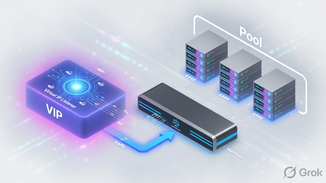
A node is an IP. A pool member is IP:port. A pool is the group plus algorithm plus monitor. A Virtual Server matches destination IP + port + protocol (and VLAN) and then uses that pool. Standard VS = full proxy, two TCP sessions.
Object hierarchy
Build bottom-up: nodes/members, then pool, then VS. Deleting a node still in a pool will refuse.
Clients send to the Virtual Server destination. BIG-IP does not “become” 10.20.20.101. It selects a member and builds a server-side connection.
Load-balancing methods
| Method | Picks | Use when |
|---|---|---|
| Round Robin | Next member in order | Equal servers, easy lab proof |
| Ratio | Weighted members | Unequal capacity |
| Least Connections | Member with fewest live connections | Long-lived sessions, mixed object sizes |
| Priority Group | Higher group first until min-members | N+M: keep backups idle until primaries die |
| Fastest / Observed / Predictive | Dynamic samples | Only after you understand the metric — Module 3 PDF flags these as advanced |
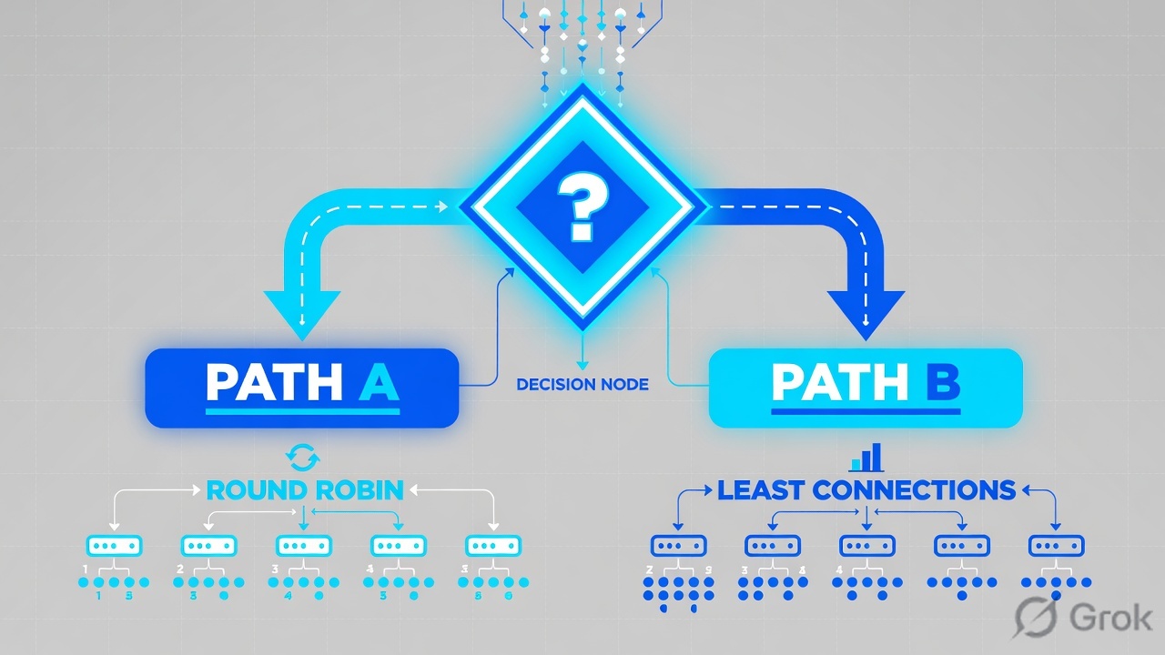
Also set Slow Ramp Time so a member just marked up does not eat every new connection, and connection limits so one server cannot be drowned. Priority Group Activation needs a minimum-active-members number or the backup group never engages.
Runbook — first HTTPS (or HTTP lab) Virtual Server
Side A · node and pool
Create or confirm nodes
GUI: Local Traffic → Nodes → Node List. A node can exist without being in a pool; a member cannot.
Create the pool
Local Traffic → Pools → Pool List → Create. Name WEB_POOL. Add 10.20.20.101–103 with the real service port.
Attach a monitor later
Module 5 builds the HTTP monitor. For this module a TCP monitor is enough to prove L4. Do not pretend ICMP means the app works.
tmsh create ltm pool WEB_POOL monitor tcp load-balancing-mode round-robin members add { 10.20.20.101:80 10.20.20.102:80 10.20.20.103:80 }
tmsh list ltm pool WEB_POOL
tmsh show ltm pool WEB_POOL membersLocal Traffic > Pools > Pool List > Create
New Pool
Source: F5-BIG-IP-LTM-Module-3.pdf and F5 cert Lab 1.
Side B · Virtual Server
Local Traffic > Virtual Servers > Virtual Server List > Create
New Virtual Server
More-specific VS wins: longer mask, explicit port, explicit VLAN. A :443 VS will not catch :8443.
tmsh create ltm virtual vs_web_http destination 192.0.2.100:80 ip-protocol tcp pool WEB_POOL source-address-translation { type automap }
tmsh list ltm virtual vs_web_http
tmsh show ltm virtual vs_web_http
Side C · verify without lying to yourself
Browser refresh is not a load-balancing test — it reuses the TCP connection. Open a new connection per request (curl in a loop, or disable keep-alive).
curl -sv --http1.0 http://192.0.2.100/ | head
tmsh show ltm virtual vs_web_http
tmsh show ltm pool WEB_POOL members
tcpdump -nni 0.0 host 192.0.2.100
Runtime after VS match
Standard VS = two sessions. FastL4 is a different type — do not mix the mental model.
Traps + proof
| Failure | Symptom | Fix |
|---|---|---|
| Said 'the VIP' meaning the pool | Wrong object in the change window | Name VS, pool, member separately |
| Port mismatch | Client 443, VS 8443, no stats | tmsh list ltm virtual destination |
| No pool attached | VS enabled, RST or timeout | Default pool field |
| Browser keep-alive | Always hits one member | curl --http1.0 in a loop |
| Member :80 vs app :443 | Monitor up, HTTP garbage | Member port is the service port, not the VIP port |
- You can draw Node vs Member vs Pool vs VS from memory.
tmsh show ltm virtualincrements on each new curl.- You know when to use Priority Groups vs Least Connections.
Knowledge check
Object words matter on a bridge call.
Sources
- Techclick PDF:
F5-BIG-IP-LTM-Module-3.pdf(from OneDrive_1_8-26-2026.zip, 26 Aug 2026) - Companion deck:
F5-Ltm-Training-Ppt (1).pptx.pdf - Official lab paths: F5 cert Lab 1 — VLANs, Self IPs, pools, virtual servers
- TMSH virtual server reference: ltm virtual
- Related deep dives on this site: SSL modes · SNAT · Persistence · VS/pools · VIP down / tcpdump
Related: Course hub · Syllabus · My Courses · F5 LTM interview