Lessons · F5 LTM series · Module 2
Full explanation — same as the Techclick PDF
This section is the workbook explanation, rewritten from BIG-IP-Networking-and-Traffic-Flow Module 2.pdf. Read it like class notes. Diagrams above are only a map — the teaching is here.
Read the PDF-order sections below. Then do the runbook. Then take the quiz. If a sentence is in the PDF, it is in this page.
PDF · page 1 — F5 BIG-IP LTM — Module 2 BIG-IP Networking & Traffic Flow
Interfaces, VLANs, Self IPs, Routing, ARP and Packet Flow Interfaces
Physical & virtual NIC fundamentals VLANs
Tagged, untagged & VLAN objects Self IPs
Port Lockdown & HA concepts Routing
Connected, static & default routes ARP
Layer-2 address resolution Traffic Flow
TMM packet processing end-to-end
PDF · page 3 — Module 2 — Learning Objectives
This module builds the data-plane networking foundation that every BIG-IP engineer must master before configuring Virtual Servers, Pools, and production applications. By the end of this module, you will be able to explain and configure every major networking layer on a BIG-IP system — from physical interfaces all the way through traffic flow and troubleshooting.
- 1 Understand BIG-IP physical and virtual networking, including interfaces and VLANs — 2 Configure VLANs (tagged and untagged), Self IPs, and verify Port Lockdown behavior
- 3 Differentiate Management IP, Self IP, and Virtual IP — and explain when each is used — 4 Understand connected routes, configure static and default routes, and explain route lookup
- 5 Understand ARP, Auto Last Hop, asymmetric routing, and full TMM traffic flow — 6 Perform packet captures with tcpdump and troubleshoot common VLAN, Self IP, ARP, and routing problems
- Prerequisites: Students must have completed Module 1 and be familiar with TMOS, TMM, MCPD, Management — IP, the BIG-IP GUI, TMSH, and basic device administration.
PDF · page 5 — BIG-IP Networking Overview
BIG-IP LTM sits logically between client networks and application servers, acting as a full-proxy intermediary that processes all traffic passing through it. Rather than simply forwarding packets at Layer 3, BIG-IP terminates connections on both sides — the client-side connection ends at the BIG-IP Virtual IP, and a separate server-side connection is initiated toward the backend. This architecture is what makes advanced features like SSL offloading, TCP optimization, and application-layer health monitoring possible.
Understanding the underlying network topology is essential before any Virtual Server or Pool configuration. BIG-IP requires correctly configured VLANs, Self IPs, and routes to be able to reach both clients and backend servers through the data plane.
Client-Side Network
- The external-facing network where clients reside. BIG- — IP presents the Virtual IP (VIP) on this side. Example:
192.0.2.0/24 Server-Side Network. The internal network hosting application servers. BIG-IP communicates with backends using its Internal Self IP.
- Example: 10.20.20.0/24
PDF · page 6 — Management Plane vs. Data Plane
Management Plane vs. Data Plane. One of the most important conceptual distinctions in BIG-IP architecture is the separation between the management plane and the data plane. These two planes are logically and physically isolated — they use different interfaces, different IP addresses, and serve completely different purposes. Confusing them is one of the most common mistakes made by engineers new to BIG-IP.
- Management Plane Path: Administrator → Management Network →
- Management IP Example IP: 192.168.100.10
Used for:
- Web GUI (HTTPS) SSH administration
REST API access iControl integrations
Carried by the dedicated Management interface (mgmt).
Does not participate in application traffic processing.
Data Plane
- Path: Client → External VLAN → TMM → Internal VLAN → Application Servers — Example IPs: Self IPs and VIPs on production VLANs Used for:
Application traffic processing Load balancing decisions
SSL offload, TCP optimization Health monitoring to backends
Carried by TMM through configured VLANs and Self IPs.
The Management IP does not replace VLAN and Self IP configuration. You must configure VLANs and Self IPs on the data-plane interfaces to handle production application traffic. Never route production traffic through the management interface.
- Management Plane Admin → Management Network → — 192.168.100.10 (GUI, SSH, API) Data Plane
- Client → External VLAN → TMM on BIG- IP → Internal VLAN → App Servers
PDF · page 7 — BIG-IP Interfaces
BIG-IP hardware appliances and Virtual Edition (VE) instances both present network interfaces to the operating system, but the underlying mechanics differ. On a hardware appliance, interfaces correspond to physical ports on the chassis — labeled using a slot.port convention such as 1.1, 1.2, 1.3. On a BIG-IP Virtual Edition, interfaces map to virtual NICs assigned by the hypervisor. The exact interface-to-NIC mapping on VE depends on the order in which virtual NICs are presented by the hypervisor, so this must always be verified during initial setup.
Each interface has properties that are important for troubleshooting and design. Link state indicates whether the physical or virtual link is active. Speed and duplex should match the connected switch or port group. The MAC address is used for Layer-2 forwarding and ARP. VLAN membership determines which VLAN objects are associated with the interface.
Key Interface Attributes Link State: Up / Down
Speed: 1G, 10G, 25G, etc.
Duplex: Full / Half MAC Address: Layer-2 identifier
VLAN Membership: Tagged or untagged assignment
TMSH Interface Commands
- # Display interface state and statistics tmsh show net interface — # Display interface configuration tmsh list net interface
- # Display a specific interface tmsh show net interface 1.1 — PRODUCTION TIP: On BIG-IP VE deployments, always verify the hypervisor port-group and VLAN configuration matches the expected BIG-IP interface assignments. A NIC-order mismatch in VMware or KVM is a very common cause of unexpected connectivity failures during initial setup.
PDF · page 8 — VMware BIG-IP VE Networking
When deploying BIG-IP Virtual Edition on VMware ESXi or vSphere, the physical-to-virtual network path involves multiple layers: physical NICs on the ESXi host, vSwitches or Distributed Virtual Switches (DVS), port groups with VLAN IDs, and finally the virtual NICs attached to the BIG-IP VM. Understanding this full stack is critical because a misconfiguration at any layer will prevent traffic from flowing — and the BIG-IP itself may show no visible error.
The mapping follows a consistent chain: VMware Port Group → BIG-IP vNIC → BIG-IP Interface → BIG-IP VLAN → Self IP. Each link in this chain must be correctly configured and aligned.
VMware Port Group VLAN ID BIG-IP Interface BIG-IP VLAN Object
F5-MGMT VLAN 30 Management (mgmt) N/A (Management plane) F5-External VLAN 10 1.1 external
F5-Internal VLAN 20 1.2 internal. TRAINER NOTE: Emphasize that the Management NIC connects to the management port group only. The dataplane NICs (1.1, 1.2) connect to their respective port groups. NIC ordering in VMware determines which vNIC maps to which BIG-IP interface number — always verify this at deployment time.
PDF · page 9 — What Is a BIG-IP VLAN?
A BIG-IP VLAN is a logical network object that represents a Layer-2 broadcast domain as understood by TMM (Traffic Management Microkernel). It is associated with one or more BIG-IP physical or virtual interfaces and provides the Layer- 2 context in which Self IPs and application traffic operate. Without a correctly configured VLAN, BIG-IP cannot participate in the corresponding network segment — even if the interface is up and the cable is connected.
In most standard deployments, at least two VLANs are created: an external VLAN that faces the client network, and an internal VLAN that faces the application server network. These correspond directly to the client-side and server-side traffic paths described in the networking overview.
External VLAN Network: 192.0.2.0/24. Faces the client-side network. Carries inbound client traffic toward the Virtual IP. Associated with interface
1.1 in a typical deployment.
Internal VLAN Network: 10.20.20.0/24. Faces the server-side network. Carries traffic from BIG-IP toward backend application servers.
Associated with interface 1.2 in a typical deployment.
- Self IP BIG‑IP Layer‑3 address on that VLAN — VLAN Object Layer‑2 broadcast domain in TMM
Interface Physical or virtual NIC bound to BIG-IP
This three-layer hierarchy — Interface → VLAN → Self IP — is the foundational building block of BIG-IP data-plane networking. Every concept in this module builds on understanding this relationship.
PDF · page 10 — Tagged vs. Untagged VLANs
Tagged vs. Untagged VLANs. BIG-IP supports both tagged (802.1Q trunk) and untagged (access) VLAN configurations on its interfaces. The choice between tagged and untagged depends entirely on how the connected switch port or virtual switch port group is configured. The BIG-IP VLAN configuration must match the switching design — a mismatch will silently break connectivity.
Untagged VLAN
Frames are sent and received without an 802.1Q VLAN tag on the BIG-IP interface. The connected switch port operates as an access port for a single VLAN.
Example A:
Interface 1.1 → Untagged member of VLAN external Switch port: Access port, VLAN 10
BIG-IP sends/receives untagged frames
Use this when each interface is dedicated to exactly one VLAN.
Tagged VLAN (Trunk). Frames include an 802.1Q VLAN tag. A single interface can carry multiple VLANs simultaneously. The connected switch port must be configured as a trunk.
Example B:
- Interface 1.1 → Tagged member of VLAN external (tag 10) — Interface 1.1 → Tagged member of VLAN dmz (tag 30) Switch port: Trunk, VLANs 10, 30 allowed
Use this when multiple VLANs must share one interface (common in VE deployments).
- Attribute Untagged Tagged (802.1Q) Frame header No VLAN tag 802.1Q tag present — VLANs per interface One only Multiple Switch port type Access port Trunk port
Typical use Hardware appliances, simple VE VE with shared NICs, trunk links
COMMON MISTAKE: BIG-IP VLAN tagging must match the connected physical switch or VMware port group configuration exactly. If BIG-IP sends tagged frames to an access port (or untagged frames to a trunk-only port), connectivity will fail with no obvious error on either side.
PDF · page 12 — VLAN Configuration
VLANs are created and managed through either the BIG-IP GUI or TMSH. Once created, each VLAN object is available for Self IP association and appears in the TMM routing and switching fabric. The VLAN name is used as a reference throughout the configuration — Self IPs, routes, and other objects refer to VLANs by name.
- GUI Path Network → VLANs → VLAN List → Create
Key fields to configure:
- Name: Logical identifier (e.g., external, internal) — Tag: 802.1Q VLAN ID (1–4094) — required for tagged VLANs
Interfaces: Select interface and set Tagged or Untagged
TMSH Commands
Create external VLAN (untagged on 1.1) tmsh create net vlan external  interfaces add { 1.1 { untagged } }
Create internal VLAN (untagged on 1.2) tmsh create net vlan internal  interfaces add { 1.2 { untagged } }
Create VLAN with 802.1Q tag (tagged) tmsh create net vlan external  tag 10  interfaces add { 1.1 { tagged } }
List VLAN configuration tmsh list net vlan
Show VLAN operational state tmsh show net vlan
PRODUCTION TIP: Interface numbers in TMSH commands must match the actual interface names on your specific appliance or VE deployment. Always run tmsh list net interface first to confirm available interface names before creating VLANs. Adapt examples to your environment — never copy-paste without verifying interface numbering.
PDF · page 13 — What Is a BIG-IP Self IP?
A Self IP is an IP address assigned to BIG-IP on a specific VLAN. It represents BIG-IP's own Layer-3 identity on that data-plane network segment. The Self IP is what allows BIG-IP to communicate directly with devices on that network — including upstream routers, backend servers, and neighboring BIG-IP devices in an HA pair.
- Every Self IP is tied to a specific VLAN object. When you assign a Self IP to the external VLAN with address — 192.0.2.10/24, BIG-IP understands that it can communicate with any host in the 192.0.2.0/24 range via that VLAN interface. Similarly, an Internal Self IP of 10.20.20.10/24 on the internal VLAN gives BIG-IP Layer-3 reachability to the
10.20.20.0/24 server network.
- External Self IP Example: 192.0.2.10/24
VLAN: external
Communicates with upstream routers, external clients
(for non-VIP traffic such as health checks), and HA peers on the external segment.
- Internal Self IP Example: 10.20.20.10/24
VLAN: internal
- Communicates with backend application servers. Used as the source for health monitors and, when SNAT — Automap is configured, as the source address for server-side connections.
Self IP Use Cases Summary
- Neighbor communication (routers, switches, HA peers) Gateway reachability and routing adjacency — Backend server communication (health monitors, pool member connections)
- BIG-IP-originated data-plane communication SNAT Automap source selection (when configured) — HA-related inter-device communication (details in Module 6)
REMEMBER: A Self IP is not the address clients use to reach your application. Clients connect to the Virtual IP (VIP) on the Virtual Server. The Self IP is BIG-IP's own address on the network — not the application service address.
PDF · page 14 — Management IP vs. Self IP vs. Virtual IP
Management IP vs. Self IP vs. Virtual IP. These three IP address types are among the most frequently confused concepts for engineers new to BIG-IP. Each serves a distinct role, operates on a different plane, and must never be substituted for another. Understanding this distinction is foundational to every configuration and troubleshooting task on BIG-IP.
- Management IP Example: 192.168.100.10 — Plane: Management Interface: mgmt (dedicated)
Purpose: Administer BIG-IP via GUI, SSH, REST API
Traffic type: Administrative only — no application data Configured during initial setup.
Reaches BIG-IP even when dataplane configuration is incomplete.
- Self IP Example: 10.20.20.10/24 — Plane: Data plane Interface: Data-plane VLAN interface
Purpose: BIG-IP's own address on a data-plane VLAN
Traffic type: Routing, health monitors, SNAT, HA communication
Always associated with a VLAN object. Represents BIG-IP on that network segment.
- Virtual IP (VIP) Example: 192.0.2.100:443 — Plane: Data plane Interface: Exists logically in TMM
(not tied to a physical interface directly). Purpose: Application service address clients connect to Traffic type: Application traffic —
HTTP, HTTPS, TCP, etc.
Defined on a Virtual Server object.
Associated with a pool of backend servers.
- CRITICAL: Management IP ≠ Self IP ≠ VIP. Never route production application traffic through the Management — IP. Never use a Self IP as a Virtual Server address for client-facing application services. Never mistake the VIP for the BIG-IP's own network address. These are three distinct, non-interchangeable concepts.
PDF · page 15 — Self IP Configuration
Self IPs are configured through the BIG-IP GUI or TMSH. Each Self IP must have a name, IP address with subnet mask, a VLAN association, a Port Lockdown setting, and a Traffic Group assignment (relevant for HA). The subnet mask is critical — it determines the directly connected network that BIG-IP will understand without requiring a static route.
GUI Path Network → Self IPs → Create. Name: Descriptive label (e.g., external_self) IP Address: IPv4 address (e.g., 192.0.2.10)
- Netmask: Subnet mask (e.g., 255.255.255.0) — VLAN / Tunnel: Select from configured VLAN objects
- Port Lockdown: Access control setting (see next section) — Traffic Group: traffic-group-local-only for non-floating
TMSH Commands
Create External Self IP tmsh create net self external_self  address 192.0.2.10/24  vlan external  allow-service default
Create Internal Self IP tmsh create net self internal_self  address 10.20.20.10/24  vlan internal  allow-service default
List Self IP configuration tmsh list net self
Show Self IP operational state tmsh show net self
- LAB TASK: After creating both Self IPs, run tmsh show net self and verify that each Self IP shows the correct — VLAN association, IP address, and subnet mask. Then run tmsh show net route to confirm that connected routes for both subnets have been automatically populated.
PDF · page 16 — Self IP Port Lockdown
Port Lockdown is a security feature that controls which BIG-IP system services (protocols and ports) are reachable through a given Self IP address. This is an important security boundary: even if an attacker can reach BIG-IP's Self IP on the network, Port Lockdown limits what they can interact with. The setting applies to administrative and managementstyle access to the Self IP itself — it is a separate concept from application traffic handled by Virtual Servers.
Allow Default
Allows access only to a platform-defined set of services considered safe for normal operations.
Recommended starting point for most Self IPs. Refer to the BIG-IP documentation for your version to see the current default service list.
Allow All
Permits any service/port to reach the Self IP. Not recommended for production-facing Self IPs. Useful only for brief troubleshooting in isolated lab environments.
Allow None
Blocks all service access to the Self IP. No administrative protocols (SSH, HTTPS, SNMP) are reachable through this address. Use for Self IPs that should be completely locked down from service access.
Custom. Allows you to explicitly specify which protocols and port numbers are permitted. Use when specific services must be allowed (e.g., SNMP from a monitoring server, BGP from a router peer) while everything else is blocked.
COMMON MISTAKE: Do not set Allow All casually on production Self IPs. This exposes BIG-IP management services (SSH, HTTPS, SNMP) to any device that can reach the Self IP on the network — including clients on the external network if the external Self IP is set to Allow All.
REMEMBER: Port Lockdown controls access to the Self IP itself. Application traffic destined for a Virtual Server (VIP) is handled by TMM based on Virtual Server configuration, not by Port Lockdown rules. These are two completely separate access control mechanisms.
PDF · page 17 — Non-Floating vs. Floating Self IP
Non-Floating vs. Floating Self IP. BIG-IP supports two categories of Self IP in an HA (High Availability) configuration: non-floating and floating.
Understanding the distinction is important even before Module 6 covers full HA configuration, because the choice affects how backend servers and routers should be configured to communicate with BIG-IP.
Non-Floating Self IP Also called: Device-specific Self IP
Traffic Group: traffic-group-local-only
Permanently belongs to a single BIG-IP device. Does not move during an HA failover event. Each device in an HA pair has its own non-floating Self IP on each VLAN.
Examples:
- F5-A Internal Self: 10.20.20.11/24 F5-B Internal Self: 10.20.20.12/24 — Used for device-specific communication (e.g., config sync, inter-device health monitoring, SSH to a specific unit).
Floating Self IP Also called: Traffic group Self IP
Traffic Group: traffic-group-1 (or custom). Associated with a traffic group and moves with whichever device is currently active for that traffic group.
Provides a stable IP that backend servers and routers can use regardless of which physical device is active.
Example:
Floating Internal Self: 10.20.20.10/24. Backend servers should use the floating Self IP as their default gateway (where BIG-IP is the gateway), because it always points to the active device.
HA PREVIEW: Detailed Active/Standby HA configuration, traffic groups, config sync, and failover behavior are covered in Module 6. At this stage, simply understand that floating Self IPs exist for HA purposes and that a non-floating Self IP is always device-specific.
PDF · page 18 — Connected Routes
When you configure a Self IP on a VLAN and assign it a subnet mask, BIG-IP automatically creates a directly connected route for the corresponding network in the route table. This means BIG-IP instantly understands how to reach any host on that subnet without requiring any manual static route configuration. The route is derived from the IP address and mask of the Self IP.
How Connected Routes Work When you create the following Self IP:
- Self IP: 10.20.20.10 Mask: /24 (255.255.255.0) — VLAN: internal BIG-IP automatically adds to its route table:
- Destination: 10.20.20.0/24 Type: Connected
Interface: internal (VLAN). This means BIG-IP can immediately forward traffic to any host in 10.20.20.0/24 — including Web01 10.20.20.101 and Web02 10.20.20.102 — without any additional route configuration.
Verification
- # Confirm connected routes appear tmsh show net route
# Example output:
- # Net Route
- # --------
- # Name Destination Type
- # internal 10.20.20.0/24 Connected
# external 192.0.2.0/24 Connected. No additional static route is needed to reach hosts on directly connected subnets. A static route is only required for remote networks that are reachable through a nexthop gateway.
REMEMBER: Connected routes are automatically created and removed as Self IPs are added or deleted. If you delete a Self IP, the connected route disappears immediately, and BIG-IP will no longer know how to reach that subnet directly.
PDF · page 19 — Static Routing
A static route manually defines a destination network and the next-hop gateway that BIG-IP should use to reach it.
Static routes are required when BIG-IP needs to forward traffic to a network that is not directly connected — meaning a network reachable only through a router or gateway, rather than being on the same subnet as a Self IP.
- When Static Routes Are Needed — If backend servers are in a remote subnet — for example,
- 10.30.30.0/24 — reachable through an internal gateway at — 10.20.20.1, a static route must be configured so BIG-IP knows where to send traffic destined for that network.
Example topology:
- BIG-IP Internal Self: 10.20.20.10 Gateway Router: 10.20.20.1 — Remote Server Net: 10.30.30.0/24 Required static route:
- Destination: 10.30.30.0/24 Gateway: 10.20.20.1 — Configuration GUI Path: Network → Routes → Create
- # Add static route via TMSH tmsh create net route \ 10.30.30.0/24 \ gw 10.20.20.1 — # List configured routes tmsh list net route
Show route table with state tmsh show net route Routes can also be deleted:
tmsh delete net route 10.30.30.0/24 Remote Network
Gateway Router BIG-IP
PDF · page 20 — The Default Route
The default route is a special static route with the destination 0.0.0.0/0. It matches any destination IP address that does not match a more-specific route in the routing table. The default route tells BIG-IP where to send traffic when no other route applies — typically the upstream default gateway.
Default Route Concept
The default route uses the longest prefix match (LPM) principle. BIG-IP always selects the most specific matching route. The default route (0.0.0.0/0) has the shortest possible prefix length, so it is only selected when no more-specific route exists.
Configuration example:
- # Set default gateway to 192.0.2.1 tmsh create net route default \ network 0.0.0.0/0 \ gw 192.0.2.1 — # Verify tmsh list net route tmsh show net route Route Lookup Decision
For any outbound packet, BIG-IP evaluates the route table in this order:
Check for a connected route (Self IP subnet match)1.
Check for a specific static route (e.g., 10.30.30.0/24)2.
Fall through to the default route (0.0.0.0/0)3.
If no route matches and no default route exists → traffic is dropped 4.
- Forward to Gateway Match Default 0.0.0.0/0
Lookup Route Table Unknown Destination
PRODUCTION TIP: A missing default route is one of the most common causes of BIG-IP being unable to reach external resources — including license servers, NTP, DNS, and remote monitoring endpoints. Always verify that a default route is configured and pointing to the correct upstream gateway.
PDF · page 21 — Route Lookup in Practice
Route lookup on BIG-IP follows the standard longest-prefix-match (LPM) algorithm. When BIG-IP needs to forward traffic, it scans the route table for the route with the most specific (longest) prefix that matches the destination IP. More specific routes always win over less specific ones, regardless of the order they were added.
Example Route Table Destination Next Hop / Type Prefix Length
- 10.20.20.0/24 Connected (internal VLAN) /24 — most specific for 10.20.20.x — 10.30.30.0/24 Gateway: 10.20.20.1 /24 — most specific for 10.30.30.x
- 0.0.0.0/0 Gateway: 192.0.2.1 /0 — matches anything else Route Lookup Examples — Traffic to 10.20.20.101 Matches 10.20.20.0/24 (connected route).
Result: Forwarded directly on the internal VLAN. No gateway needed.
Traffic to 10.30.30.55 Matches 10.30.30.0/24 (static route).
Result: Forwarded to gateway 10.20.20.1.
Traffic to 8.8.8.8 No specific match found.
Matches default route 0.0.0.0/0.
Result: Forwarded to 192.0.2.1.
- INTERVIEW QUESTION: "What determines which route BIG-IP uses when multiple routes could match?" — — Answer: The longest prefix match. The most specific (longest subnet mask) matching route wins. If two routes have the same prefix length, administrative distance and metric may apply depending on the source.
PDF · page 22 — ARP — Address Resolution Protocol
ARP (Address Resolution Protocol) is the Layer-2/3 glue that maps an IPv4 address to a MAC address on a local network segment. Before BIG-IP can forward an IP packet to any directly connected device — whether a backend server, a router, or an HA peer — it must first resolve that device's MAC address through ARP. Without a valid ARP entry, BIG-IP cannot deliver the frame at Layer 2, even if the routing table shows the correct path.
ARP Process Example
BIG-IP needs to send traffic to Web01: 10.20.20.101 BIG-IP checks its ARP table for 10.20.20.1011.
No entry found — BIG-IP broadcasts an ARP request:
"Who has 10.20.20.101? Tell 10.20.20.10" 2.
Web01 responds with its MAC address3.
BIG-IP caches the mapping in its ARP table4.
BIG-IP can now forward frames to Web015.
ARP Commands
- # View BIG-IP ARP table (TMSH) tmsh show net arp
- # View ARP from bash shell arp -an — # View neighbor table (Linux style) ip neigh
- # Sample ARP table entry: — # Name Address HWaddress Vlan
- # /Common 10.20.20.101 00:50:56:ab:12:34 /Common/internal — Symptoms of ARP Problems Symptom Likely Cause
- ARP entry shows "Incomplete" Target host not responding — down, wrong subnet, or VLAN mismatch — No ARP entry for backend server Layer-2 connectivity issue, wrong interface, or switch config problem
- ARP resolves but traffic fails Firewall blocking, wrong VLAN tag, or routing asymmetry — Duplicate IP warning in ARP IP address conflict — two devices using the same IP on the segment
PDF · page 23 — BIG-IP Traffic Flow Through TMM
Understanding exactly how a packet travels through a BIG-IP system end-to-end is the most important conceptual skill in this module. All application traffic passes through TMM (Traffic Management Microkernel) — the BIG-IP data-plane engine that handles Virtual Server matching, connection management, policy enforcement, and backend selection. The flow below describes a standard HTTPS connection from a client to a Virtual Server backed by a pool of servers.
01 DNS Resolution. Client (198.51.100.50) resolves the application hostname to the Virtual IP:
- 192.0.2.100 02 — Client Sends TCP SYN Client initiates a TCP connection to
192.0.2.100:443. The frame arrives at BIG-IP's external VLAN interface.
03 TMM Receives Traffic. TMM receives the frame on the external VLAN. It processes the packet and matches it against configured Virtual Servers.
04 Virtual Server Match. BIG-IP matches the packet to the Virtual Server configured for
192.0.2.100:443. LTM processing begins — profiles, iRules, and policies are evaluated.
- 05 Backend Selection
LTM selects a pool member (e.g.,. 10.20.20.101:443) based on the loadbalancing algorithm and health monitor status.
- 06 BIG-IP Opens Server-Side
Connection
- BIG-IP initiates a new TCP connection to 10.20.20.101:443 from its internal — VLAN. Route and ARP resolution occur for the backend.
07 Traffic Exits Internal VLAN. The request exits BIG-IP through the internal VLAN interface and arrives at
Web01 (10.20.20.101).
- 08 Backend Responds
Web01 sends its response back to
BIG-IP's internal Self IP (or SNAT address). BIG-IP receives, processes, and correlates the response with the client-side connection.
09 Response Returned to Client. BIG-IP forwards the response on the client-side connection back to the originating client (198.51.100.50).
NEXT MODULE: Virtual Server configuration, pool members, load-balancing algorithms, and health monitors are covered in detail in Module 3.
PDF · page 24 — Client-Side vs. Server-Side Connections
Client-Side vs. Server-Side Connections. BIG-IP LTM operates as a full proxy. This means it maintains two completely separate TCP connections: one on the client side (between the client and the VIP) and one on the server side (between BIG-IP and the backend server). The two connections are independently managed by TMM and are joined together logically inside BIG-IP. This architecture is what enables many of BIG-IP's most powerful features — the client and server never communicate directly.
Client-Side Connection Endpoints:
- Client 198.51.100.50 ↔ BIG-IP VIP 192.0.2.100:443 — BIG-IP terminates this connection. All client-facing TCP,
SSL, and HTTP behavior is determined here. The client believes it is communicating directly with the application server.
- Client TCP profile applies here Client SSL profile (if HTTPS) applies here — Persistence cookies may be set here Server-Side Connection
Endpoints:
BIG-IP ↔ Backend 10.20.20.101:443. BIG-IP originates this connection. The backend server sees BIG-IP (or a SNAT address) as the source. The backend is unaware of the original client's IP unless X-
Forwarded-For or SNAT is configured appropriately.
Server TCP profile applies here
- Server SSL profile (for re-encryption) applies here Connection pool / OneConnect may apply here — This full-proxy model is why BIG-IP can apply different TCP window sizes, SSL cipher suites, and connection behaviors independently on each side. It is also why correctly understanding the return path (server-side back to BIG-IP, then BIG-
IP back to client) is critical — which leads directly to the next topic: return path and asymmetric routing.
PDF · page 25 — Return Path & Symmetric Routing
For stateful TCP connections, it is critical that return traffic flows back through the same BIG-IP device that handled the initial connection. BIG-IP maintains connection state — including TCP sequence numbers, SSL session data, and persistence tables — and it can only properly handle the response if it sees both directions of the traffic flow. This is the concept of symmetric routing.
- BIG‑IP → Client Server → BIG‑IP BIG‑IP → ServerClient → BIG‑IP — Ensuring Symmetric Return — Server Default Gateway
The most common and reliable way to ensure return traffic passes through BIG-IP is to configure backend servers to use BIG-IP's internal Self IP (or floating Self IP in HA) as their default gateway. When the server sends response traffic, it sends it to BIG-IP, which then forwards it to the client on the correct client-side connection.
Correct Backend Gateway Design Backend server (Web01):
- IP: 10.20.20.101 — Default Gateway: 10.20.20.10 ← BIG-IP Internal Self IP
When responding to any IP not in 10.20.20.0/24,. Web01 forwards the packet to BIG-IP → Symmetric ✓ Problem Gateway Design
Backend server (Web01):
- IP: 10.20.20.101 — Default Gateway: 10.20.20.1 ← Some other router
When responding, Web01 may bypass BIG-IP entirely.
- Response arrives at client from unexpected path → Asymmetric — PRODUCTION TIP: Before deploying a BIG-IP Virtual Server, always verify the default gateway configuration on backend servers. If the server's gateway points to a router other than BIG-IP, return traffic may bypass BIG-IP and cause intermittent failures or complete connection drops.
PDF · page 26 — Asymmetric Routing
Asymmetric routing occurs when the outbound path and the return path of a TCP connection do not pass through the same device. In a BIG-IP deployment, this typically means the client's request arrives at BIG-IP and is forwarded to the backend server — but the server sends its response directly back to the client through a different router, completely bypassing BIG-IP. Since BIG-IP never sees the return traffic, it cannot correlate the response with the connection state it maintained for the request.
Asymmetric Flow (Problematic) Client 198.51.100.50 → BIG-IP VIP 192.0.2.100 → Web01 10.20.20.101 ✓ 1.
- Web01 sends response → Router (bypassing BIG-IP) → Client directly ✗
2.
BIG-IP never sees the server's response3.
BIG-IP connection state becomes invalid4.
Potential Consequences TCP connection reset or timeout
Excessive TCP retransmissions
- Intermittent application behavior (works sometimes) — BIG-IP connection-state mismatch / stale sessions
- SSL handshake failures (BIG-IP never receives server hello) — Health monitors may pass while application fails Common Design Solutions
Option 1 — Fix the Return Route
Configure backend servers to use BIG-IP's internal
Self IP (or floating Self IP) as their default gateway.
This ensures all return traffic passes through BIG-IP.
This is the preferred solution when the network design allows it.
Option 2 — Use SNAT
- When BIG-IP performs SNAT (Source NAT) on the server-side connection, the backend server sees BIG- — IP's Self IP as the source. The server's response is automatically returned to BIG-IP regardless of its default gateway. SNAT is appropriate when fixing the return route is not possible. SNAT configuration is covered in detail in Module 4.
IMPORTANT: SNAT is not always required — it is a solution for the asymmetric routing problem. If backend servers are correctly configured to use BIG-IP as their gateway, SNAT may not be necessary. Always evaluate both options based on your network design.
PDF · page 27 — Auto Last Hop
Auto Last Hop (ALH) is a BIG-IP feature that records the Layer-2 MAC address of the device that sent traffic to BIG-IP, and then uses that MAC address to return traffic back to the same device — rather than performing a standard route lookup to determine the next hop for the return path. This can be useful in certain directly connected client-side scenarios where the standard routing decision might send return traffic through a different path than expected.
How Auto Last Hop Works
- When a packet arrives at BIG-IP, ALH records the source MAC address of the incoming frame. When BIG- — IP sends return traffic for that session, instead of performing a routing table lookup to determine the egress interface and next-hop MAC, BIG-IP forwards the return frame directly to the recorded MAC address.
This means the return traffic goes back to the specific
Layer-2 device that originally sent the packet — the "last hop" before BIG-IP — regardless of what the routing table says.
Practical Considerations
- ALH can simplify return forwarding in scenarios where a client-side router or firewall sends traffic to — BIG-IP, and you want responses to go directly back to that same device
ALH is not a substitute for correct overall routing design
ALH does not solve all asymmetric routing scenarios
- — particularly when the asymmetry involves serverside return paths — ALH behavior should be validated against your specific BIG-IP software version and network architecture
In some complex multi-path or ECMP environments,
ALH may interact with routing in unexpected ways
- REMEMBER: Auto Last Hop is enabled by default on most BIG-IP configurations and applies at the Virtual — Server or global level. While it provides a convenient shortcut for return forwarding in simple topologies, it should not be relied upon as the primary mechanism for ensuring symmetric routing. Correct routing design on backend servers remains the most reliable approach.
PDF · page 29 — Route Domains — Introduction
Route Domains are an advanced BIG-IP feature that allows the system to maintain separate, isolated routing and network namespaces within a single BIG-IP device. Each Route Domain has its own independent routing table, allowing the same IP address space to exist in multiple Route Domains simultaneously without conflict. This is particularly useful in multi-tenant environments, managed service provider deployments, or when consolidating multiple networks with overlapping IP address ranges onto a single BIG-IP platform.
Route Domain Basics
Every BIG-IP has a default Route Domain with ID 0. All standard configurations (VLANs, Self IPs, Virtual Servers) operate in Route Domain 0 unless explicitly assigned to another Route Domain.
- Route Domain membership is indicated by appending %
PDF · page 30 — Packet Capture Basics — tcpdump on BIG-IP
Packet capture is one of the most powerful diagnostic tools available to a BIG-IP administrator. By capturing traffic directly on the BIG-IP system, you can observe exactly what packets are arriving and leaving, verify that traffic is hitting the correct VLAN, confirm that ARP is resolving, and diagnose connection failures at the protocol level. BIG-IP uses the standard Linux tcpdump tool, with some BIG-IP-specific interface conventions.
Essential tcpdump Commands
- # Capture all traffic on all TMM interfaces tcpdump -nni 0.0 — # Capture traffic to/from a specific host tcpdump -nni 0.0 host 10.20.20.101
- # Capture traffic on a specific port tcpdump -nni 0.0 port 443 — # Capture for specific host AND port tcpdump -nni 0.0 \ 'host 198.51.100.50 and port 443'
# Save capture to file for Wireshark analysis tcpdump -nni 0.0 -s0 \ -w /var/tmp/module2.pcap
PDF · page 31 — Network Troubleshooting Command Reference
The following commands form the core diagnostic toolkit for BIG-IP network troubleshooting. TMSH commands provide visibility into BIG-IP object configuration and operational state. Shell commands provide packet-level and system-level diagnostic capability. Developing fluency with both sets of tools is essential for efficient BIG-IP troubleshooting.
Interfaces tmsh show net interface tmsh list net interface
Check link state, speed, duplex, and error counters for all physical and virtual interfaces.
VLANs tmsh show net vlan tmsh list net vlan
Verify VLAN objects, interface membership, tagging, and VLAN IDs. Confirm VLAN-to-interface mapping.
Self IPs tmsh show net self tmsh list net self
Verify Self IP addresses, subnet masks, VLAN associations, Port Lockdown settings, and traffic group assignments.
Routes tmsh show net route tmsh list net route
Inspect the active route table. Confirm connected routes, static routes, and default gateway are present and correct.
ARP tmsh show net arp arp -an ip neigh
Check ARP resolution for backend servers, routers, and HA peers. Look for Incomplete or missing entries.
- Packet Diagnostics ping <host> traceroute <host> ip route tcpdump -nni 0.0 host <ip> — Test connectivity, trace routing paths, verify the active system route table, and capture packets at the TMM level.
REMEMBER: Use TMSH for BIG-IP object and state visibility. Use shell tools (ping, traceroute, tcpdump, ip) for packet-level and network-path diagnostics. Both are necessary for complete troubleshooting — neither alone is sufficient.
PDF · page 32 — Hands-On Lab Topology
The following topology is used for all Module 2 lab exercises. All IP addresses follow RFC 5737 documentation conventions for external/public ranges and RFC 1918 for internal ranges. Verify your lab environment matches this topology before beginning lab tasks.
Component IP Address VLAN / Network VMware Port Group
- BIG-IP Management 192.168.100.10/24 Management (VLAN 30)F5-MGMT — BIG-IP External Self 192.0.2.10/24 external (VLAN 10) F5-External
BIG-IP Internal Self 10.20.20.10/24 internal (VLAN 20) F5-Internal External Gateway 192.0.2.1 external F5-External
- Lab Client 198.51.100.50 Client network External/Client — Web01 10.20.20.101 internal (VLAN 20) F5-Internal
- Web02 10.20.20.102 internal (VLAN 20) F5-Internal
PDF · page 33 — Lab Tasks — Module 2
Complete the following tasks in sequence. Use both the GUI and TMSH to gain familiarity with both interfaces. Validate each step using the verification commands before proceeding to the next task. Task 13 is intentional — you will break a working configuration and then troubleshoot it back to working state.
1 Verify Interfaces. Run tmsh show net interface. Confirm all expected interfaces show link state Up.
- 2 Create External VLAN — Create VLAN external on interface 1.1 (untagged).
Verify with tmsh list net vlan.
- 3 Create Internal VLAN — Create VLAN internal on interface 1.2 (untagged).
Verify with tmsh show net vlan.
4 Configure External Self IP. Create Self IP 192.0.2.10/24 on VLAN external. Port Lockdown: Allow Default.
5 Configure Internal Self IP. Create Self IP 10.20.20.10/24 on VLAN internal. Port Lockdown: Allow Default.
- 6 Verify Port Lockdown — Review the Port Lockdown setting on each Self IP.
Confirm neither is set to Allow All.
7 Verify Connected Routes. Run tmsh show net route. Confirm 192.0.2.0/24 and 10.20.20.0/24 appear as connected routes.
- 8 Configure Default Route — Add default route to 0.0.0.0/0 via gateway 192.0.2.1.
Verify in route table.
9 Ping Backend Servers. From BIG-IP shell: ping 10.20.20.101 and ping 10.20.20.102. Both should respond.
10 Check ARP Table. Run tmsh show net arp. Confirm MAC addresses are resolved for both backend servers.
11 Run tcpdump. Run tcpdump -nni 0.0 host 10.20.20.101. Ping Web01 from another terminal and observe ARP and ICMP in the capture.
12 Verify Packet Flow. Save a capture to /var/tmp/module2.pcap and analyze it. Confirm traffic enters the correct VLAN.
13 Break a Configuration. Intentionally misconfigure one element (e.g., change internal VLAN interface or delete a Self IP). Observe the failure.
14 Troubleshoot and Restore. Use the troubleshooting commands to identify the root cause. Restore the correct configuration and verify all connectivity is restored.
PDF · page 35 — Troubleshooting Scenarios
The following scenarios represent the most common networking problems encountered in BIG-IP environments. Work through each scenario systematically using the decision logic below. These scenarios are also suitable for lab practice — intentionally recreate each failure condition and practice the resolution.
Scenario 1 — BIG-IP Cannot Ping Backend
Server Check in order:
Interface link state: tmsh show net interface 1.
VLAN configuration and interface membership: tmsh list net vlan 2.
Internal Self IP exists and correct subnet: tmsh list net self 3.
Subnet mask correct — is the backend in the same subnet? 4.
ARP resolved? tmsh show net arp 5.
Switch/VMware port group VLAN config matches BIG-IP
VLAN tag setting 6.
Backend server firewall or iptables blocking ICMP 7.
Scenario 2 — ARP Remains Unresolved
Check in order:
Is the target IP in the same subnet as the Self IP? 1.
VLAN tagging match — is
BIG-IP using tagged when switch expects untagged? 2.
VMware port group VLAN ID matches BIG-IP VLAN tag 3.
Target server powered on and network service running 4.
Duplicate IP — is another device using the same IP? 5.
Layer-2 path — is the switch port trunk/access configured correctly? 6.
Scenario 3 — External Works, Internal Does Not
Check in order:
Internal interface link state Up
1.
Internal VLAN exists and assigned to correct interface 2.
Internal Self IP configured and correct subnet 3.
VMware port group F5- Internal config — correct
VLAN ID 4.
Connected route for internal subnet present: tmsh show net route 5.
Backend server network config — correct IP/gateway 6.
Scenario 4 — Request Reaches Backend, Client
Never Gets Response Investigate:
Backend server default gateway — does it point to BIG-IP?
1.
Asymmetric routing — is response bypassing BIG-IP? 2.
Firewall between backend and BIG-IP blocking return traffic 3.
Is SNAT configured — does the backend see BIG-IP as source? 4.
Run tcpdump on both external and internal to trace the full flow 5.
Scenario 5 — VE Interface Up But No
Traffic Passes Check in order:
Verify vNIC order — does
BIG-IP interface 1.1 map to the expected VMware vNIC? 1.
VMware port group assigned to the correct vNIC 2.
Port group VLAN ID matches BIG-IP VLAN tag setting
3.
VMware promiscuous mode, forged transmit, and MAC changes settings (as applicable) 4.
tcpdump on 0.0 — do any frames arrive? If not, the problem is below BIG-IP in the vSwitch/physical layer
5.
PDF · page 36 — Interview Questions & Answers — Module 2
The following questions cover the core concepts of this module. These are representative of questions asked in F5 technical interviews, certification examinations, and peer technical reviews. Study the answers and ensure you can explain each concept in your own words — not just recite definitions.
Q1: What is a BIG-IP VLAN?
A BIG-IP VLAN is a logical network object representing a Layer-2 broadcast domain. It is associated with one or more BIG-IP interfaces and is used by TMM for data-plane traffic processing.
VLANs are the foundation for Self IP assignment and network segmentation.
Q2: What is a Self IP?
A Self IP is an IP address assigned to BIG-IP on a specific VLAN. It represents BIG-IP's own Layer-3 identity on that network segment, enabling communication with routers, backend servers, and HA peers on the data plane.
Q3: Management IP vs. Self IP?
The Management IP is on the dedicated management interface and is used exclusively for administrative access (GUI, SSH, API). A Self IP is on a data-plane VLAN and is used for production network communication. They are completely separate — one does not replace the other.
Q4: Self IP vs. VIP?
A Self IP is BIG-IP's own address on a VLAN — used for routing, health monitoring, and BIG-IP-originated communication. A VIP (Virtual IP) is the application service address that clients connect to — it is defined on a Virtual Server object and represents the loadbalanced service, not BIG-IP's own address.
- Q5: What is Port Lockdown? Port Lockdown controls which BIG-IP services — (protocols/ports) are accessible through a Self IP.
Options include Allow Default, Allow All, Allow None, and Custom. It is a security boundary for administrative/service access to the Self IP itself — not a control for application traffic handled by Virtual Servers.
Q6: What is a floating Self IP?
A floating Self IP is associated with a traffic group and moves between devices during an HA failover. It provides a stable address that backend servers and routers can rely on regardless of which physical BIG- IP device is currently active. Detailed HA configuration is covered in Module 6.
PDF · page 37 — Interview Questions & Answers — Continued Q7: Floating vs. Non-Floating Self IP?
- Interview Questions & Answers — Continued Q7: Floating vs. Non-Floating Self IP? — A non-floating (device-specific) Self IP belongs permanently to one device and does not move during failover. A floating Self IP is associated with a traffic group and moves to the active device during failover.
Both are needed in an HA pair — non-floating for device-specific access, floating for application traffic and backend gateway use.
Q8: Tagged vs. Untagged VLAN?
Untagged: Frames carry no 802.1Q tag — used when the interface connects to an access port carrying a single VLAN. Tagged: Frames carry an 802.1Q VLAN tag — used when one interface carries multiple VLANs (trunk port). The BIG-IP VLAN tag configuration must match the connected switch or port group exactly.
Q9: What is a directly connected route?
A directly connected route is automatically created when a Self IP is configured with a subnet mask. It tells BIG-IP that the corresponding subnet is reachable directly through the associated VLAN interface, without needing a gateway or next hop. No manual route entry is required.
Q10: What is a default route?
A default route (0.0.0.0/0) defines where BIG-IP should send traffic when no more-specific route matches the destination. It is the route of last resort, typically pointing to an upstream gateway or firewall.
Without a default route, BIG-IP drops traffic to unknown destinations.
Q11: What route wins when multiple routes exist?
The most specific route — the one with the longest prefix length (longest subnet mask) — always wins.
This is called longest-prefix match (LPM). A /24 route wins over a /16 route, and both win over the default route (/0), even if the default route was added first.
Q12: What is ARP?
ARP (Address Resolution Protocol) maps an IPv4 address to a MAC address on a local Layer-2 segment. BIG-IP uses ARP to resolve the MAC address of backend servers, upstream routers, and HA peers before it can deliver frames at Layer 2.
Without ARP resolution, IP-level forwarding cannot occur on directly connected networks.
PDF · page 38 — Interview Questions & Answers — Final Set Q13: How do you view BIG-IP ARP entries?
- Interview Questions & Answers — Final Set Q13: How do you view BIG-IP ARP entries? — Use tmsh show net arp for BIG-IP object-level ARP table visibility. Use arp -an or ip neigh from the bash shell for system-level ARP/neighbor table. Look for
Incomplete entries, which indicate unresolved neighbors.
Q14: What is asymmetric routing?
Asymmetric routing occurs when the outbound and return paths of a TCP connection pass through different devices. In BIG-IP deployments, it typically means the client's request goes through BIG-IP but the server's response returns via a different router, bypassing BIG-IP entirely. This breaks stateful connection processing and causes TCP failures, retransmissions, or connection drops.
Q15: How can SNAT help with the return path?
When SNAT is applied, BIG-IP replaces the client's source IP with its own IP (Self IP or SNAT pool address) before sending the packet to the backend.
The server sees BIG-IP as the source and automatically returns the response to BIG-IP — regardless of the server's default gateway. This eliminates the asymmetric routing problem without requiring a gateway change on the servers. SNAT details are covered in Module 4.
Q16: What is Auto Last Hop?
- Auto Last Hop records the Layer-2 MAC address of the device that sent traffic to BIG-IP, and uses that — MAC to return traffic — rather than performing a routing table lookup. It can help in certain directly connected scenarios, but it is not a substitute for correct routing design and does not solve all asymmetric routing problems.
Q17: What is a Route Domain?
- A Route Domain is a BIG-IP feature that creates an isolated network/routing namespace. Multiple Route — Domains can exist on a single BIG-IP, each with its own routing table. The same IP address can exist in different Route Domains simultaneously, identified by the %domain-id suffix (e.g., 10.10.10.10%1). Route
Domain 0 is the default.
Q18: How do you capture packets on BIG- IP?
Use tcpdump from the BIG-IP bash shell. Interface 0.0 captures across all TMM VLAN interfaces simultaneously. Use filters like host and port to scope the capture. Use -s0 -w /var/tmp/file.pcap to save fulllength packets to file for Wireshark analysis.
Q19: What does tcpdump interface 0.0 provide?
Interface 0.0 on BIG-IP is a special capture point that allows observing traffic across all TMM VLAN interfaces in a single capture session. This means you can see both client-side and server-side traffic without needing to run separate captures on individual VLAN interfaces. It is the most comprehensive single capture point available on BIG-IP.
Q20: What should you check when BIG-IP cannot reach a backend server?
- Check in order: (1) Interface link state, (2) VLAN configuration and interface assignment, (3) Internal — Self IP address and subnet mask, (4) Connected route for the backend subnet in the route table, (5) ARP resolution for the backend IP, (6) Switch/VMware port group VLAN configuration, (7) Backend server firewall or OS-level filtering. Run tcpdump to confirm whether frames are reaching the BIG-IP interface.
PDF · page 39 — Module 2 — Revision Checklist
Use this checklist to confirm your understanding before proceeding to Module 3. You should be able to explain each concept clearly, configure it in both the GUI and TMSH, and troubleshoot common failures related to it. Check off each item only when you can confidently do all three.
Networking Fundamentals
Explain the difference between the management plane and data plane Describe BIG-IP interface numbering conventions
(hardware vs. VE). Explain the Interface → VLAN → Self IP hierarchy Create a VLAN (tagged and untagged) via GUI and
- TMSH — Explain when to use tagged vs. untagged VLAN configuration
Configure a Self IP and associate it with a VLAN
Differentiate Management IP, Self IP, and Virtual IP
Explain Port Lockdown options and when to use each
- Explain floating vs. non-floating Self IP and their HA purpose Routing, ARP & Traffic Flow — Explain how directly connected routes are automatically created Configure a static route via GUI and TMSH
- Configure a default route and explain its purpose Explain longest-prefix-match route selection — Explain ARP and troubleshoot common ARP failures Explain Auto Last Hop at a practical level
Explain asymmetric routing and its impact on BIG-IP
Describe two solutions to the asymmetric routing problem
Explain BIG-IP Route Domains at an introductory level Traffic Flow & Diagnostics
- Trace a complete client-to-server packet flow through TMM (9 steps) — Explain the full-proxy model and client-side vs.
- server-side connections — Run tcpdump on BIG-IP interface 0.0 with appropriate filters
Save a packet capture to a file for Wireshark analysis Troubleshooting
Use all TMSH network verification commands fluently
- Diagnose BIG-IP-to-backend connectivity failures Identify and resolve ARP resolution failures — Identify asymmetric routing from a symptom description
Diagnose VMware VE interface / port group mismatches
- MODULE COMPLETE: When all checklist items are checked, you are ready for Module 3 — Nodes, Pools, — Virtual Servers & Load Balancing. In Module 3, you will build on this networking foundation to configure the application delivery objects that make BIG-IP LTM a production load balancer.
PDF · page 40 — Next Module Module 3
Nodes, Pools, Virtual Servers & Load Balancing
With the data-plane networking foundation from Module 2 fully in place, Module 3 configures the application delivery objects that make BIG-IP LTM a production load balancer. You will define pool members, configure Virtual Servers, apply health monitors, and observe how BIG-IP distributes traffic across backend servers using multiple load-balancing algorithms.
Nodes & Pool Members
Define backend servers as BIG-IP objects. Understand the difference between a node and a pool member.
Pool Configuration. Create load balancing pools, assign members, and configure health monitors to ensure traffic only goes to healthy backends.
Virtual Servers
Configure Virtual Server objects — the client-facing component that receives traffic on the Virtual IP and directs it to a pool.
Load Balancing Algorithms
Understand Round Robin, Least Connections, Priority
Group, and other methods. Choose the right algorithm for each use case.
Same lab numbers on every page: client 198.51.100.50, VIP 192.0.2.100, Self IPs 192.0.2.10 / 10.20.20.10, members 10.20.20.101–103.
- Hub · Course map
- M1 · Fundamentals & admin
- M2 · Networking & traffic flow ← you are here
- M3 · Virtual Servers & pools
- M4 · Profiles, SNAT, SSL
- M5 · Monitors, iRules, policies
- M6 · High availability
- M7 · Troubleshooting
Next → M3 · Virtual Servers & pools
Recorded course + workbooks: My Courses · syllabus F5 LTM / GTM / ASM
Wiring before Virtual Servers
Module 1 gave you a licensed box. Module 2 gives TMM a path to clients and servers. If VLANs, Self IPs, or routes are wrong, every later object looks broken: empty ARP, no pool members, mysterious timeouts.
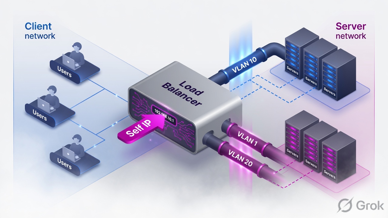
Create matching VLANs (tagged or untagged exactly as the switch), put a Self IP on each VLAN with Port Lockdown Allow Default, confirm connected routes and ARP, then — and only then — build a Virtual Server. Never put application traffic on mgmt.
Mental model
Client-side network presents the VIP. Server-side network reaches pool members. TMM terminates the client connection on the VIP and opens a new connection from a Self IP (or SNAT address) toward the server.
Auto Last Hop remembers the MAC that sent the frame so replies can return even when routing is ugly.
Port Lockdown limits services on the Self IP. It does not filter Virtual Server traffic. Allow All on a production Self IP exposes admin services to the data plane.
Tagged vs untagged, Port Lockdown, routes
| Choice | Use when | Fail mode |
|---|---|---|
| Untagged | Switch access port / untagged port-group, one VLAN | Sending 802.1Q into an access port = silent drop |
| Tagged | Trunk / 802.1Q, multiple VLANs on one NIC | Forgetting the tag on vSphere port-group |
| Allow Default | Almost every production Self IP | See version-specific default service list |
| Allow None | Self IP must not offer services | You can still publish VIPs on that VLAN |
| Allow All | Brief isolated lab only | Mgmt services reachable from app VLAN |
Runbook — two VLANs that actually pass traffic
Side A · interfaces and VLANs
See the NICs TMM owns
tmsh show net interfacethentmsh list net interface. VE: confirm the hypervisor mapping. A vNIC swapped in VMware is a classic silent fail.Create VLANs to match the switch
GUI: Network > VLANs. Lab: external untagged on 1.1, internal untagged on 1.2.
If the switch is a trunk
Use tagged + the VLAN ID the switch already uses. BIG-IP tag and switch tag must be the same number.
tmsh create net vlan external interfaces add { 1.1 { untagged } }
tmsh create net vlan internal interfaces add { 1.2 { untagged } }
# trunk example
# tmsh create net vlan external interfaces add { 1.1 { tagged } }
tmsh list net vlan
tmsh show net vlanNetwork > VLANs > Create
New VLAN
Source: BIG-IP Networking and Traffic Flow Module 2.pdf. Tag mismatch with the switch is the most common Module 2 outage.
Side B · Self IPs and Port Lockdown
tmsh create net self external_self address 192.0.2.10/24 vlan external allow-service default
tmsh create net self internal_self address 10.20.20.10/24 vlan internal allow-service default
tmsh show net self
Network > Self IPs > Create
New Self IP
Port Lockdown = services on this Self IP. Virtual Server traffic is a different control.
Side C · routes, ARP, Auto Last Hop
Connected subnets appear after Self IPs. Remote subnets need statics. Default route is for unknown destinations (often internet or a client supernet).
tmsh create net route 10.30.30.0/24 gw 10.20.20.1
tmsh create net route default gw 192.0.2.1
tmsh show net route
tmsh show net arp
Auto Last Hop records the Layer-2 MAC of the device that sent traffic to BIG-IP and sends the reply back to that MAC. It is enabled by default on most systems and saves you when the L3 return path would otherwise be asymmetric. Do not disable it as a “cleanup” step.
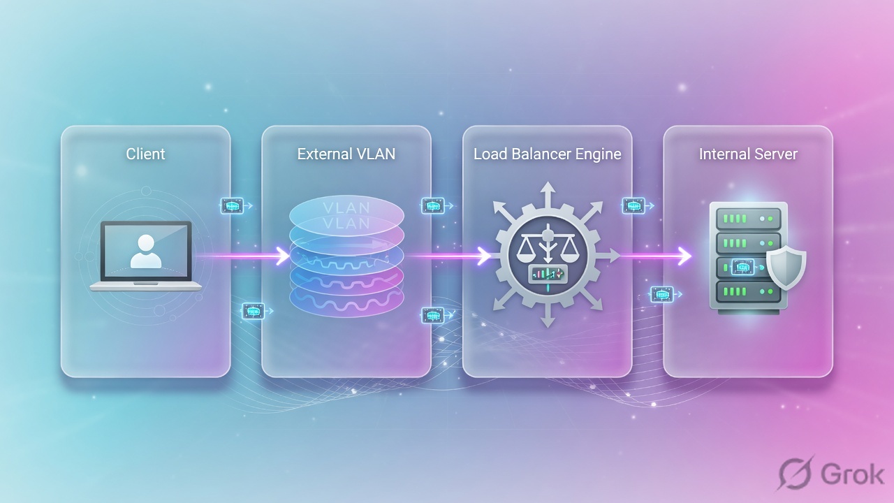
Runtime path and tcpdump
Interface 0.0 is the TMM 'all VLANs' tap. Filter by host so you can read it.
tcpdump -nni 0.0 host 198.51.100.50
tcpdump -nni external host 192.0.2.10
tcpdump -nni internal host 10.20.20.101
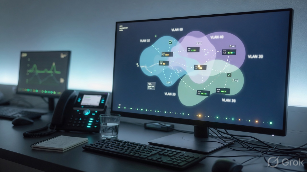
Traps + proof
| Failure | Symptom | First check |
|---|---|---|
| Tag mismatch | NIC up, no ARP, no traffic | Switch/port-group tag vs BIG-IP tagged/untagged |
| App on mgmt | Users cannot hit VIP | VIP and Self IP are data-plane objects |
| Allow All Self IP | Scanner finds HTTPS/SSH on app VLAN | Set Allow Default or Allow None |
| Missing default route | Outbound or remote clients blackhole | tmsh show net route |
| VE NIC swap | Traffic on the 'wrong' VLAN | tmsh show net interface vs hypervisor |
tmsh show net selfshows both Self IPs on the right VLANs.- ARP exists toward a lab server on the internal VLAN.
- You can explain Port Lockdown without mentioning Virtual Servers.
Knowledge check
Wiring questions. If you miss Port Lockdown, re-read Side B.
Sources
- Techclick PDF:
BIG-IP-Networking-and-Traffic-Flow Module 2.pdf(from OneDrive_1_8-26-2026.zip, 26 Aug 2026) - Companion deck:
F5-Ltm-Training-Ppt (1).pptx.pdf - Official lab paths: F5 cert Lab 1 — VLANs, Self IPs, pools, virtual servers
- TMSH virtual server reference: ltm virtual
- Related deep dives on this site: SSL modes · SNAT · Persistence · VS/pools · VIP down / tcpdump
Related: Course hub · Syllabus · My Courses · F5 LTM interview